airwalk se
original directions for use
Development, production, sales & service
h/p/cosmos sports & medical gmbh Am Sportplatz 8
DE 83365 Nussdorf-Traunstein Germany
phone +49 86 69 86 42 0
fax +49 86 69 86 42 49
email@h-p-cosmos.com www.h-p-cosmos.com
© 2014 h/p/cosmos sports & medical gmbh All rights reserved
h/p/cosmos sports & medical gmbh Am Sportplatz 8 DE 83365 Nussdorf-Traunstein / Germany phone +49 / 86 69 / 86 42 0 fax +49 / 86 69 / 86 42 49 email@h-p-cosmos.com www.h-p-cosmos.com file: n:\article\cos30017man-v1_0-en\20141029_cos30017-01_manual_h-p-cosmos_airwalk_se_en_v1_3.doc
© 2014 h/p/cosmos sports & medical gmbh created 29.10.2014 printed 29.10.2014 page: 1 of 79
This manual is only valid for the firmware-/software version noted on the first page of this manual and only for the original configuration of the first delivery of the machine.
Firmwareupdates, softwareupdates, changes of the system configuration or retrofittings of additional equipment or accessories can result in invalidity of this manual. In case of alterations of the device or the additional equipment always the actual version of the manual or the according additional information has to be considered.
[1.]Introduction
Dear customer,
We would like to express our gratitude for putting your trust in us, in deciding for this hight standard the unweighing system. Since 1988 we have been developing and manufacturing running machines for sports and medical application. When it comes down to technology, design and safety, we have set extremely high standards for ourselves.
Because the unweighting device is a motor-driven and powerful device, you must pay special attention to the mentioned safety regulations. If proper notice is taken of the safety regulations, the operation of our unweighting device is almost without any risk. The neglect of the safety regulations could result in dangerous situations and serious accidents. Therefore please carefully read the installation and operation manual and the danger precautions before taking the device into operation.
Simple maintenance, if described, can easily be done by yourself. We recommend to call our competent service team or entering into a maintenance contract for a routine service in an interval of 6 or 12 months. A form for registration of your institution and device is included in the delivery folder. In order to be able to supply you with the latest technical information and service, it is important for you to fill out the form. Please fill out the form for registration immediately and send it back via fax.
The instruction manual as a firm part of the delivery has to be accessible for all users at any time. This instruction manual has been written with great care. Should you, however, still find any details, which do not correspond with your device, please give us notice, so that we can correct any mistakes as soon as possible. Subject to alterations without prior notice,
We wish you a lot of fun and success while exercising and working with your h/p/cosmos unweighting device.
h
Franz Harrer
President
h/p/cosmos sports & medical gmbh
Comment:
The unweighting device h/p/cosmos airwalk se is compatible with below listed running-machine series.
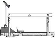
h/p/cosmos 150/50 locomotion DE med
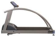
h/p/cosmos mercury
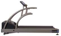
h/p/cosmos quasar
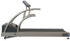
h/p/cosmos pulsar
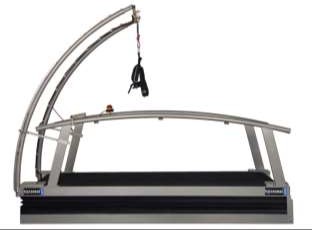
h/p/cosmos venus 200/75if mounted in a pit
[2.]Content
[4.] Safety, warnings, precautions, prohibitions 10
[3.A] Safety precautions, safety regulations, prohibitions and warnings 10
[3.D] General Instructions / Safety 11
[3.E] Instructions for safety and operation 13
[3.E1] Electric safety / Safety classes 13
[3.E2] Patient security according to VDE 0750 (IEC 601-1) type B 13
[3.E3] Potential equalization 13
[3.E4] Connection of units installed outside medically utilized locations 14
[3.E5] Medical electrical systems 14
[3.E6] Subject's surroundings 14
[3.E7] Protection against the danger of electrical shocks 15
[3.E8] Environmental requirements 15
[3.H] Safety standards, norms 16
[3.H2] EMC Electromagnetic Compatibility 17
[3.I] Fields of application / intended use 18
[3.I1] Professional application in sports and fitness 18
[3.I2] Professional application in the medical field 18
[3.I3] h/p/cosmos devices - MDD medical device directive. Safety standards 18
[3.I4] Forbidden use - contraindications 21
[5.] Installation & commissioning 23
[5.A] Transport, unpacking and packaging 23
[5thB] Transport to upper floors and through narrow doors 23
[5.C] Mechanical installation 24
[5.D] Electrical installation 25
[5thD2] Electric safety measurements and „First Measured Values“ 26
[5.D3] Potential equalization 26
[5.E] Starting the unweighting device 28
[5.E1] Switching the device on 28
[5.E2] Switching the device off 28
[5.F] Installation, Overview, Checklist 28
[6thA] Controlelements and displays: Manual control unit and housing unweighting unit. 37
[6thA1] Manual control unit of Levi unweighting unit 37
[6thA2] Displays of the Levi unweighting unit and the connection for manual control 38
[7.A2] Verwendete Laufbänder und Rollstuhlrampen: 39
[7.A3] Before starting training 39
[7.B] h/p/cosmos airwalk Vests 40
[7thC] Attaching the Vest to the Unweighting Bar 44
[7.C1] Correcting Vest Problems 44
[7.D] Velcro-Gait Control Straps 44
[7thD1] Internal Foot Rotation, Excessive Stride Length 45
[7.D2] External Foot rotation 45
[7thE] Putting on the h/p/cosmos airwalk Vest for Wheelchair Patients 46
[7thF] Entering the unweighting device – supportign weight / standing up 47
[7thG]Setting the support weight and range of motion 47
[7.H] General advice for training 49
[7.I] Unweighting / weight support 49
[7.L] Trainingduration/ distance und training frequency 50
[7.M] Training troubleshooting 50
[7thO]At the end of a training day 51
[7.P] Patient documentation 51
[7.Q] Patient becomes unconscious 51
[8.] Maintenance and safety inspections 52
[8.A] Preventiv maintenance 53
[8.B] Immediate maintenance 53
[8.C] Regular inspections/examinations 53
[8thC1] Visual inspection dirt / damage – daily before training 54
[8thC2] Emergency release unweighting device – every 3 months 54
[8thC3] Running machine – follow manufacturers guidelines 54
[8thC4] Changing the rope – min. every year 55
[8thC6] Protective Earth Resistance RPE measurement 56
[8.C7] Isolation Resistance RISO measurement 57
[8thC8] Equivalent (alternative) leakage current IEDL measurement 57
[8thC9] Electric Safety Tester an measurements 57
[8thC10] Building installation: Electric Checks, Protective Earth Function, RCD, Leakage Current 58
[9.A] Mechanical / Noise problems 59
[9.B1] Electrostatic Discharge 59
[9.B2] Source of Interference 60
[9thC] Voltage at the device housing / electric shock 60
[9thC1] Open (interrupted) earth wire / ground – shown here on the esample of a running machine 60
[9.D] Electrical interference 61
[10.] Technical specifications 62
[10thA] h/p/cosmos airwalk se 62
[10thB] EMC electromagnetic compatibility. Guidance and manufacturer's declaration 64
[11.] accessories and options 66
[11thA] Vests for subjects for h/p/cosmos airwalk and h/p/cosmos airwalk se 66
[11.C]h/p/cosmos running machines 66
[11.D]Safety multiple socket 66
[13.A] Disassemble and cut up 67
[13thB] h/p/cosmos unweighting devices 67
[15.] Appendix – Instruction and commissioning 69
[15.A] Calibrating the unweighting indications 69
[15.B] Instruction into general operation 69
[15.C]Instruction into functions 70
[15thD] Instruction in maintenance works and safety checks 72
[15.E] Advice and support documents 73
[15thF] Confirmation of commissioning and introduction / instruction 74
[15.G]Service report – cos15531 75
[15.H]Control protocol – cos15533 76
[15thJ] Protocol for maintenance on h/p/cosmos airwalk se 78
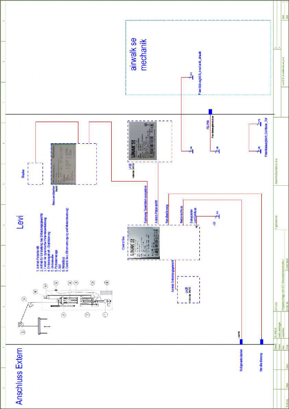
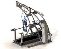
The h/p/cosmos airwalk devices are made of powder coated steel. Two vertical sidebars carry the traverse with the deviating pulley. Like a crane the device is overlapping the treadmill in a height of approximately 2,5m.
The unweighting unit is integrated into the system. It may either be a mechanic (winch / spring), pneumatic (pneumatic cylinder) or electric (servo motor) unit performing the weight support. The unweighting force is transferred via a static rope to the unweighting bar. The patient is wearing a special vest, which is fixed to the unweighting bar.
In order to support the patient, the unweighting vest is similar to a climbing harness with a very high degree of comfort.
Application
In neurological rehabilitation it is important for the patient to start exercising as early as possible. Therefore an individual and optimal un-weighting system is crucial for the patient. The h/p/cosmos airwalk unweighting system supports a natural gait pattern. The single-point suspension allows dynamic vertical movement when walking and at the same time allows freedom in movement and body rotations where wanted. Additional fixation straps for further stabilization may be utilized if desired and if recommended for the patient. The unweighting, depending on the progress of therapy, can be adjusted via a hand unit.


[4.]Safety, warnings, precautions, prohibitions
[3.A] Safety precautions, safety regulations, prohibitions and warnings
N Anyone not involved in the training session must keep at least a safety distance of 2 meters away from any part of the system.
N The Levi unweighting unit must only be combined with the h/p/cosmos airwalk se. Don´t use any unweighting device which has not been installed or checked by h/p/cosmos.
N Training must only be carried out with closed front door of the Levi unweighting unit housing.
N Check that the deflection pulleys are turning freely erery time before using the equipment. Do not carry out training if the deflection pulleys are jammed. If a jam occurs during a training session, stop the session immediately.
N Training with the h/p/cosmos airwalk se may only be carried out by a trained user who has read the user manual. This person must be present at all times to supervise the training session when the system is being used for training.
N The unweighting device is approved for patients with a maximum body weight of kilograms. Heavier patients must not be trained with the h/p/cosmos airwalk se.
N Make sure, before opening the unweighting vest, that the patient is no longer being supported.
N Check the support bar, the unweighting vest and the rope for any damage before every training session. If one of these parts is damaged, treatment of the patient must not be started or continued.
N If there are faults or anomalies or if there is evidence of damage (e.g. unusual sounds), the training session must be stopped immediately and a h/p/cosmos authorized technician must be informed without delay.
N In the event of a power failure the patient must be lowered using the emergency release. Do not continue training until proper operation is guaranted.
N If the patient can not be lowered for technical reasons (winch and emergency release are no longer working), do not attempt to remove the patient from the device on your own. Ask for assistance from one or more people you have called upon, and they can lift the patient while you then undo the buckles on the unweighting vest.
N The unweighting device may only be used if maintenance has been carried out properly according to the instructions included in this user manual.
N If a wheelchair ramp in combination with a treadmill (option) is used, make sure that the ramp is clean and correctly placed on the treadmill.
N You will find further sayfety instructions in part [6.M] of this user manual.
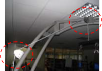
[3.B] Danger zones
No. | Illustration | Description |
Illustration shows possible danger zones: there may be a risk of beeing jammed by incorrect and/or inattentive use. Please be careful and follow all safety instructions. |
[3.C] Emergency release
N To activate the emergency release, you must pull the knob out slowly.
N It is important to observe the patient all the time when doing this to ensure that he is lowered in a controlled manner. If possible, a second user should support the patient, while the other user is activating the release.
N Release the knob when the patient has been lowered to the desired level.
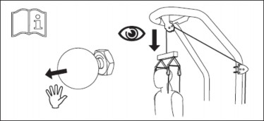
Diagram showing how to use emergency release
| You must pull out the knob very carefully to enable you to control the speed at which the patient is being lowered (the speed when lowering heavy patients tends to be greater than when lowering light patients). |
| A regular check (every three months) must be carried out to see that the emergency release is in good working order |
[3.D] General Instructions / Safety
This instruction manual is part of the device and must always be accessible for every user.
Exact observance of the instruction manual is a requirement for the appropriate operation of an h/p/cosmos device.
| Important notes, warnings and safety precautions are marked with the opposite sign. It also reminds you of concerns which have to be considered for measurements and connection with other devices.. |
The safety of your subjects and the compliance to the mentioned accuracy of measurement can only be achieved, if the consumption goods, described in the instruction manual, are being used and the recommended preventive maintenance and safety checks are performed by personnel authorised by h/p/cosmos.
Absorption-, cleansing- and disinfecting chemicals are only to be kept in the appropriate reservoirs. At the connection of gas pressure container it has to be examined about its MOT-admissibility (TÜV) first. Pull the plug before cleansing or disinfecting electric devices.
Safety, reliability and function can only be achieved if ...
N installation, extension, alteration and repair is performed by authorized people. N the room for installation corresponds to the DIN and VDE installation directives. N the device is plugged in at a socket with a protection system.
N the room for installation corresponds to the requirements of the surroundings for the device.
N the device after the instruction is being used in accordance with the instruction manual.
The entry of fluid into the device has to be removed immediately by the authorized customer service and a safety examination has to be performed. Damaged socket connections, wires and pressure control switches have to be replaced instantly by trained personnel or by authorised persons.
| In case of any detected and/or assumed malfunctions and/or defects or unreadable safety warning labels the device has to be taken out of operation, the device has to be marked and secured against operation (for example pull power plug and affix warning/defect label on the power plug) and the supplier and authorised service personnel has to be informed in writing. |
[3.E] Instructions for safety and operation
The regulations mentioned in this chapter refer to the Federal Republic of Germany. For all other states take into account the national legislation. If the running machine is a sports device (only c mark without 4-digit number), it must not be connected with a medical product and must not be used for medical purposes. Due to higher safety requirements medical instruments and devices are not allowed to be connected via extension cable and/or multiple plug socket with the power supply, and a medical product must not be connected with a sports device either.
| Disregard of warnings, disregard of intended and forbidden use, safety precautions and also unauthorized or lack of maintenance and/or regular safety checks may lead to injuries or even death and/or can damage the device and will result in loss of any liability and warranty |
[3.E1] Electric safety / Safety classes
In order to protect the subject (athlete and/or patient) and the personnel, the association of German electro- technicians Inc, (VDE) has published special directives for medical used rooms and electro-medical devices. Devices with a power supply therefore have to, in order to prevent the passing on of the mains voltage over to touchable metal pieces, be equipped with not only a reliable isolation of the parts being under voltage but also additional safety precautions. The VDE-association divides it into so called safety classes.
Of the, for electro-medical devices, licensed safety classes are mainly used the safety class I (i.e. safety precautions with protective wiring), and the safety class II, (i.e. safety measures without protective wiring but with double isolation): Devices of the safety class I are devices, where the metallic casing-parts are connected with the protective wire of the line net via the safety contact. In the case of an isolation error the inserted fuse element switches off.
[3.E2] Patient security according to VDE 0750 (IEC 601-1) type B
If your h/p/cosmos device has a c mark with a 4-digit number (e.g. n) at the identification plate, it is a medical product. At your h/p/cosmos medical product the patient is protected/isolated from the mains in accordance with the safety standard referring to the requirements for leakage current values according to IEC 601- 1 type B. The connection of further mains-operated units to your h/p/cosmos-unit may cause that all the leakage currents add and the safety of the patient is reduced. Due to this the connection of further units may only be carried out on consultation with h/p/cosmos.
[3.E3] Potential equalization
The connection of e.g. EDP units to the V24 / RS 232 / USB / LAN / FireWire interface of the computer or of other independent measuring stations can only be carried out in medically utilized locations according to VDE 0107 / EN ISO 60601-1-1. Parallel connection of the potential equalization ensures, that in case of insulation failure none of the connected units exceeds a voltage of 10mV and thus endangers the patient.
For this purpose all of the h/p/cosmos units are equipped with a connection fixture with which the equipotent conductor, being part of the standard equipment, is connected to the equipotent bus bar of the room.
Standard potential equalization cable (length 5m) with 4mm2 cross-section [cos10223]
[3.E4] Connection of units installed outside medically utilized locations
If units installed outside medically utilized locations (e. g. external printer, host computer etc.) are connected to an h/p/cosmos unit installed in a medically utilized location the VDE 0750 regulations must be observed. Connection only via …
Optical fibre or optocoupler (4 kV checked and approved) or …
Protective isolation via insulation transformer according to IEC 601-1, appendix k. These units are to be connected to the equipotent conductor.
Due to the increased safety requirements medical instruments may not be connected via extension leads or multi- way connectors.
[3.E5] Medical electrical systems
The medical electrical system (later in this text referred as “system”) is a combination of several devices, of which at least one is a medical electrical equipment. A combination occurs when devices are connected via so called “functional connections” or via a mobile multiple socket. Not only electrical connections are defined as “functional connections” but also those for the transmission of signals, electrical energy and/or substances. Thus already the operation of two or more devices on the same multiple outlet is defined as a system. Even a mechanical connection or a wireless connection produces a medical electrical system.
Basically it is imperative that a system is as safe as a single medical electrical equipment. The requirements in the medical devices act and the applicable regulations (for example MPBetreibV) must be met. The system as a whole must ensure that within the patients environment or at contact with patients the same level of safety prevails, as determined by DIN EN 60601-1 (VDE 0750 Part 1).
[3.E6] Subject's surroundings
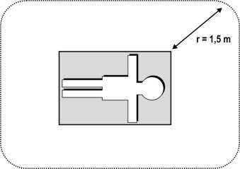
The surroundings of the subject must have a gap of 1.5 m as it has been proofed by experience. This has been laid down here as the surrounding.
[3.E7] Protection against the danger of electrical shocks
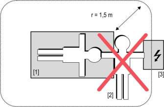
Casing and cover: Parts of non-medical electric devices within the surrounding of the subject, which, after having taken off the coverings etc. without the use of tools for a routine maintenance etc., are in touchable reach, have to operate with a voltage that does not exceed 25 volt alternate voltage and 60 volt direct voltage, which is produced by a separate source as described in IEC 601-1. According to this example the leakage current would flow from the electric device
to the earthened subject via the trainer/doctor.

[3.E8] Environmental requirements
Unweighting devices are not to be used in medically utilized rooms with a danger of explosions or in easily inflammable atmospheres. The devices must not be installed near to e.g. an x-ray device, motors or transformer with high connection power, as the electric and magnetic interference can falsify measurements or even make them impossible. High voltage lines must be avoided nearby the device. h/p/cosmos electrical devices with mains connections must neither be used in wet and humid areas (e.g. swimming pool, sauna, etc.) nor in environmental chambers.
If not stated otherwise in the delivery information h/p/cosmos devices are designed for operation in normal climatic surroundings (DIN IEC 601-1):
N Temperature: + 10° ... + 40° C
N Relative humidity: 30 ... 70 % (non condensing!)
N Air pressure: < 1.5 bar (approx. 10,000 feet (3000m), without pressurization)
The system has to be protected from high humidity. Venting slots are not to be covered; otherwise it would hinder the air circulation. Store the devices at a temperature of – 20° ... + 50° C.
All devices can be stored without power-connection and without operation for a period of 6 – 9 months. After this period batteries in the device may be discharged and maintenance and/or a new setup/programming of the device could required by authorized h/p/cosmos technician.
[3.F] Economic life-time
The economic life time of the product is determined at common usage and application to 20 years, provided that after 10 years all electrical parts and component, as well as mechanical parts like for example deflection pulleys, are renewed (at damage or unusual heavy duty possibly earlier) and the recommended maintenance intervals are kept. Every maintenance and repair work needs to be carried out by authorized h/p/cosmos technicians. For expendable parts a shorter life-time is due.
[3.G] Symbols used
All symbols used comply with the according norms IEC417, IEC878, EN957-1:2005 and Council Directive 2002/96/EC.
| Read manufacturer’s guide, advises, instructions and manual | M | Protection ground |
| Warning / safety precautions Pay attention to accompanying instructions | N | Earth |
R | Devices of the type B | P | Potential compensation |
J | Dangerous electric voltage |
| Symbol for collection, treatment, recycling and disposal of waste electrical and electronic equipment (WEEE) as set out in Directive 2002/96/EC of 27 January 2003 of the European Parliament and of the Council on waste electrical and electronic equipment are necessary to reduce the waste management problems linked to the heavy metals concerned and the flame retardants concerned. |
T | Alternating current (AC) | ||
N | Bullet point | ||
| Symbol based on ISO7010:2003-M002. Follow manufacturer’s guide, advice, instructions in the manual. Manual contains relevant safety information. |
[3.H] Safety standards, norms
All h/p/cosmos unweighting devices are produced according to strict safety- and quality controls. The product must not be used, if the certificates/permissions and the (according to the list of technical specifications) defined safety standards do not correspond with the local and country-specific requirements. The country-specific requirements must be compared before initial operation. Operate unweighting device only, if the requirements correspond. Full list of applicable norms see also in the CE-certificate of compliance.
The standards with date in this manual with reference to design and construction characteristics, refer to the up to date valid versions at the time of manufacture.
The standards with date in this manual applying to routine measurements and continual safety relevant measures (e.g. electrical measurements to determine leakage current, insulation resistances etc.) can and will change with time. Therefore the up to date valid versions of the respective standards at the time of measurement and their limit values, which can deviate then from the procedures and limit values in this manual, apply.
The c mark on the nameplate of the sports and fitness running machines confirms the compliance to the council directive 89/336/EEC appendix I (EMC electromagnetic compatibility). The audit has been conducted after the criterion of jamming and interference immunity.
[3.H2] EMC Electromagnetic Compatibility
The unweighting devices for medical applications (with n mark) have been built corresponding to the European Union Council Directive 93/42/EEC
Norms: EMC: EN60601-1-2; EN61000-3-2; EN61000-3-3, Safety: EN60601-1
Certification bodies: RWTÜV Systems GmbH, D-45032 Essen
Strong electromagnetic fields, transmitters and interferences, which are above the normal tolerance, can interfere with measuring fuctions and displays of the running machines and can lead to other malfunctions.
[3.H3] General advice
The device is assigned to overvoltage-category II and pollution level I.
[3.I] Fields of application / intended use
[3.I1] Professional application in sports and fitness
The unweighting device h/p/cosmos airwalk se is a medical device. The user is free to use the system for sports and fitness applications.
See professional application in the medical field
[3.I2] Professional application in the medical field
The purpose of using the h/p/cosmos airwalk se is to support treadmill training being used to treat patients with walking disabilities caused by cerebral, neurogenic, spinal, muscular or bone-related disorders.
The h/p/cosmos airwalk se can be used with the following patient conditions in particular:
Intended use / indications
Intended use
N Body weight support of a subject (during treadmill therapy/training)
N Fall protection of a subject (during treadmill therapy/training)
N Emergency stop in case of falling during treadmill therapy/training
N Balance training under unweighted and/or secured conditions
N Functional movement and gait training under unweighted and/or secured conditions
N Overspeed/hyperspeed and excess frequency training in athletics
Indications
According to: Johanna Jasper-Seeländer “Laufbandtherapie in der motorischen Rehabilitation”
N Hemiparesis
N Paraplegia
N Multiple Sclerosis
N Craniocerebral injury
N Further not inherent neurologic gait dysfunctions
N Parkinson's disease
N Rheumatism
N Orthopedically / surgically caused indications
N Amputations
N Complete Paraplegia with chip implantation
N Inherent gait dysfunctions
Just as for any other therapy, the physician in charge is always responsible for indicating treadmill training. The under section [3.I4] listed contraindications must be taken into account for training on the h/p/cosmos airwalk se.
[3.I3] h/p/cosmos devices - MDD medical device directive. Safety standards
Over 20 years of experience in the production of treadmill-ergometers and complex systems with accessories and special options have made h/p/cosmos the absolute treadmill specialist. We consider ourselves as the “market precursor in technology and safety” amongst all treadmill manufacturers. Safety has a very high priority for us –
because we know from experience what kind of accidents can occur and which consequences might result from these accidents.
An unweighting device is a very effective instrument in rehabilitation, therapy, diagnostics and other applications. However, like in many areas of daily life (i.e. all kinds of traffic, may it be by car, train or bus or the handling of electrical machine tools etc.) the use of a device such as an unweighting device involves dangers which can be minimized by abiding strictly to safety procedures, but can never be fully excluded. As a manufacturer it is h/p/cosmos’ duty, and as the distributor or end-user/operator of the unweighting device it is your duty, to minimize those dangers as good as possible.
In medical applications with the combination of unweighting devices and running machines many additional risks have to be considered. These risks consider on hand to the connection to the system via the unweighting vest (fresh scars from surgeries, material in bones etc.) and on the other hand the therapy on the running machine and caused exercise (patients with pacemakers, ECG lead and electrode connections to the skin, health and physical limitations, high workloads during stress tests, medication, etc.). Therefore medical treadmills with interface and interactive heart rate based load controls are classified as risk class IIb medical devices. They have specific additional design characteristics compared to fitness treadmills, and can only be sold and serviced by authorized and certified distributors. h/p/cosmos has the responsibility to ensure that the systems are correctly installed (with usage instruction) and maintained. The unweighting device is classified in risk class IIa, but is in case of the conjunction to a running machine regarded as a IIb product.
Therefore we have implemented a medical device observation and reporting system based on the statutory obligations contained in, Guideline 93/42 EEC, MDD (medical device directive), ISO9001 and EN13485 standard and our internal safety policy and risk management system. This is of utmost importance and all our distributors must sign a contract that they will comply with these important international rules for medical devices, particularly for class IIb devices and their respective statutory requirements.
h/p/cosmos fulfils its duty in different ways:
N All medical unweighting devices have to undergo an internal product-type examination as well as external tests performed by the respective examination institutes such as the TUV Product Service in Munich / Germany or the EMC laboratory. Our medical treadmill-ergometers meet the norms and guidelines stipulated for medical applications such as the, MDD, EU guideline 93/42 EEC for medical products, IEC EN 60601-1 (VDE 0750), VDE 0751, EN 61000-6-1 and EN61000-6-3 (EMC) and EN 10535 (patient lifters)
N All h/p/cosmos products must undergo a detailes test after production. All tests are recorded, checked by a second independent employee and filed. h/p/cosmos treadmills have to pass the checks 100% without exception.
N h/p/cosmos has a quality management and risk management system according to ISO 9001:2000 & ISO 13485:2003 as well as medical device observation and incident reporting system.
N In the course of maintenance work h/p/cosmos technicians or authorised service personnel check the electrical safety of the unweighting device together with all safety relevant details and measure the accuracy of speed and elevation of the treadmills at the customer’s premises.
N h/p/cosmos trains all relevant service technicians and sales personnel as medical device consultants with respective certification.
N The user manuals of h/p/cosmos unweighting devices contain all important information and safety advice as well as maintenance instructions and user regulations. The unweighting devices have a label with the date of the next safety check /maintenance.
Therefore we take it as our responsibility to inform our partners and customers about the background and necessity only to use medical products in the medical application field. Statutory requirements only permit us to supply medically classified equipment for medical applications.
Medical Device Directive Article 1 Definitions, scope 2 a.)
“medical device” means any instrument, apparatus, appliance, material or other article, whether used alone or in combination, including the software necessary for its proper application intended by the manufacturer to be used for human beings for the purpose of: Diagnosis, prevention, monitoring, treatment or alleviation of disease, diagnosis, monitoring, treatment, alleviation of or compensation for any injury or handicap, investigation, replacement or modification of the anatomy or of a physiological process, control of conception, and which does not achieve its principal intended action in or on the human body by pharmacological, immunological or metabolic means, but which may be assisted in its function by such means;
The use of a product not released for medical use by the manufacturer in a medical application can result in increased risks for the patients and for the operator – especially in the case of an accident on the treadmill ergometer. In this case all parties involved (your insurance company, your professional association, possibly patients lawyers and courts) will question negligence and liability. Therefore the use of a sports device for medical purposes bears increased risks for the distributor, customer, operator, end user and last but not least the patient. Despite that some of the above mentioned laws and guidelines are only binding within the European Union, the patient’s needs, the risks and the required safety procedures are the same all over the world. We ask all parties involved to help in improving safety.
[3.I4] Forbidden use - contraindications
Like for any other therapy, the physician in charge is always responsible for indicating treadmill training. The following contraindications must be taken into account for training on the h/p/cosmos airwalk se:
Absolute contraindications:
N Acute myocardial infarction (within 2 d)
N Instable angina pectoris
N Cardiac arrhythmia pathology and/or limited hemodynamics
N Symptomatic massive aortic stenosis
N Uncompensated / uncontrolled heart insufficiency
N Acute pulmonary embolism or pulmonary infarction
N Acute endocarditis, myocarditis, pericarditis
N Acute aortic dissection
N Acute coronary syndrome
N Acute phlebothrombosis of the lower extremities
N Febrile infections
N Pregnancy
N Acute thrombosis
N Fresh wounds e.g. after surgery
N Acute fracture
N Damaged disc or traumatic disease of the spine
N Epilepsy
N Inflammations
N Acute migraine
Relative contraindications:
N Left main coronary stenosis
N Main artery disease
N Cardiac valve disease of moderate severity
N Known electrolyte imbalance
N Arterial hypertonia (RR > 200 mm Hg syst. > 110 mm Hg diast.)
N Tachyarrhythmia or bradyarrhythmia
N Hypertrophic cardiomyopathy and other forms of outflow tract obstruction
N Higher degree atrioventricular AV-blocking
N Anemia
N Physical and/or mental disabilities leading to inability to exercise adequately
Also see following guidelines:
Deutsche Gesellschaft für Kardiologie – Herz- und Kreislaufforschung e.V. (http://leitlinien.dgk.org). American College of Cardiology Foundation - www.acc.org
American Heart Association - www.americanheart.org
http://my.americanheart.org/idc/groups/ahaecc-internal/@wcm/@sop/documents/downloadable/ucm_423807.pdf Further contraindications may occur. This has to be evaluated by the responsible medical doctor.
The above list does not claim to be exhaustive. The decision as to whether a patient is suitable for treatment always comes under the remit of the physician in charge, who has sole medical responsibility for the treatment. As part of this, he must evaluate in particular, in each individual case, possible risks and side-effects of the treatment against the benefit gained from it. In addition, the patient’s individual situation plays just as important a role as the basic risk assessment for specific patient groups.
Being a scientific discipline, medicine is subject to constant change in response to new knowledge and progress. It is therefore the task of the physician in charge to continually keep his knowledge up to date by reading the latest scientific literature and to acquire new knowledge during the course of treatment.
| At the suspicion of unauthorized access or other reasons to lock the unweighting device, the system has to be locked, signed as „blocked“ and secured against use (for example, unplug the power cord and to affix warning label). |
[5.]Installation & commissioning
[5.A] Transport, unpacking and packaging
When receiving the machine in a crate or unpacked, make sure the machine, the accessories and/or the packaging is not damaged. If you discover any damage and/or missing parts make a note on the packing-list / delivery note of the carrier. Inform h/p/cosmos and your dealer immediately in writing about any damages and/or missing parts.
| The manufacturer does not undertake any liability for any damage, complaints and missing parts which is not reported immediately by delivery on the packing-list / delivery note. |
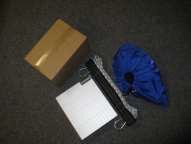
Before you unpack the machine and accessories read instructions on the crate. Make sure that the machine, power connection cable or any optional equipment will not be damaged during unpacking. Pay special attention on small parts, so that you do not dispose them or any instructions with the packaging. Within Germany mostly all devices are delivered and assembled by h/p/cosmos directly or by an authorised forwarder. If delivered by h/p/cosmos the packaging will be taken back and recycled.
If the unweighting device is being delivered by a carrier, you can recycle the packaging yourself or send it back to the manufacturer (transportation is to be paid by the customer). Often a recyclable transport tool or packaging or a transport-fuse (metal angle with screws) is included in the extent of delivery.
Ask your dealer and the carrier to take the packaging and the recyclable transport tool back to your dealer or to h/p/cosmos at your own costs. In some cases a credit note can be granted. Special packaging and/or carrier constructions must not be disposed unauthorized.
[5thB] Transport to upper floors and through narrow doors
The unweighting device is usually delivered on a h/p/cosmos standard pallet (L: 275cm x W: 1,22cm x H: 170cm) with a crate. The pallet can either be brought in fully loaded through doors with a minimum width of 135cm with the help of a forklift truck or a handlift truck, or the single parts can be carried in by hand to the future location.
| Some of the components weigh between 45 and 80 kg. Please notice, that the installation must be done by h/p/cosmos authorized technicians. |
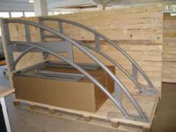
Possile way of delivery on pallet in a crate.
.

[5.C] Mechanical installation
N In order to ensure proper installation and safety, either the manufacturer, an authorised service crew or an authorised dealer must always perform transport and installation of the devices
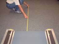
N For security reasons behind the unweighting device is a safety area of at least 2m x 1m length and width or a minimum of the width of the equipment must be free for space to move. Should a treadmill (option) be us in conjunction with a wheelchair ramp, in this case the safety zone is to measure from the end of the wheelchair ramp. In case of the option of reverse belt rotation, you must note that also the area in front of the treadmill is a safety area. So even in front of the treadmill, a safety area of at least 2 mx 1 m as a free fall space is required.
N The provided space for the unweighting device must be even and horizontal.
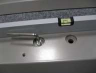
N Models with leveling sockets (adjustable "feet") at the rear of the unweighting device have to be adjusted so that they have a firm stand, otherwise it could lead to noises like knocking or rattling during the training. Check the level arrangement with a water-level at al axes on the frame.
N The bearing capacity of floor and ceiling in the building must be higher than the weight of the machine. It has to be approved for the h/p/cosmos device by an authorized body of the operator. Example h/p/cosmos airwalk se in standard configuration vor running machice h/p/cosmos mercury: Dimensions ground frame unweighting device: L: 2230 mm x B: 2070 mm = 4.62 m² platform. Net weight of unweighting device: 390 kg, additionally running machine: app. 200 kg; static bodyweight of subject: 200 kg, dynamical weight of subject: 1200 kg (up to 6 times the bodyweight), over all weight load of system at platform: 1790 kg = bearing capacity of platform: 387.45 kg (~ 400 kg) / m².
[5.D] Electrical installation

N Installation of any electrical device and h/p/cosmos devices and running-machines must only be carried out at a voltage power connection with ground wire (earthing) including leakage-current protection-switch (interrupter) and according to VDE 0100 or/and the currently valid regulations and directives. Requirements for special locations, areas and establishments (e.g. medically used areas) must be strictly adhered. PE-connection (protection-earth- contact) is stipulated at all running-machines. The voltage drop between the beginning of the consumer’s installation and the wall socket must not be more than 4% (DIN VDE 0100-520). It is the consignee’s and user’s personal responsibility to check the correct functions of the mains connection including the outlets and an authorized electrical engineer must check these points for perfect functions regularly (1 ... 4 years). Inspections of the electrical installations within the building are not incumbent on the supplier h/p/cosmos.
N As standard, a usual power supply of 230 Volt / AC, 50/60 Hz is sufficient for most of the running machines.
N Use a usual 16 Ampere expulsion fuse with C-tripping-circuit for your house distribution.
N For further questions please ask your electrical engineer or h/p/cosmos.
N Before installing the unweighting device please compare the specifications on the nameplate concerning the mains voltage and the mains frequency with your local characteristics. Connection only if identical.
N Check the main lead, the voltage power supply outlet and ground wire protection-contacts before plugging it in. Damaged leads and couplers and defective or dirty contacts have to be exchanged immediately. Rubber-leads can get porous and friable after some years.
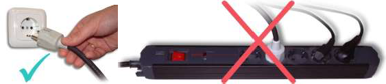
N Plug the device directly into the wall socket with checked ground wire. Each device has to be connected to a separate circuit. The socket has to be marked with name and serial number of the running machine. The use of an extension cables or a multiple plug sockets is not allowed.
N Electrical devices with mains connections must neither be used in wet and humid areas
[5.D1] Name plate
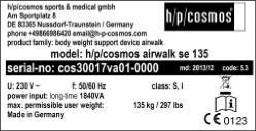
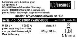
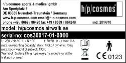
Example name plate h/p/cosmos airwalk se
For full details please refer to the chapter „technical data“ in this manual.
Devices produced until 01.01.2014 are labeled according with article number cos30017vaxx. cos30017va01 was the airwalk se with treadmill support, cos30017va02 without treadmill support.
The new article number cos30017-01 is just the same as the former cos30017va02 (without treadmill support).
[5thD2] Electric safety measurements and „First Measured Values“
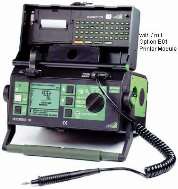
Immediately at first installation at the customer’s site an electric safety test and measurement has to be performed for „Protective Earth Resistance“,
„Isolation Resistance“ and „Leakage Current“ and the values have to be recorded on a special protocol [cos11690xx] and marked with „first measured values“. For details please refer to the chapter „maintenance / inspections“ in this manual. One copy of this protocol [cos11690xx] remains at the owner’s manual and the original of the protocol with the
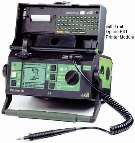
„first measured values“ shall be sent to the manufacturer h/p/cosmos. Picture: Example for electric safety testing device based on IEC 601-1
[5.D3] Potential equalization
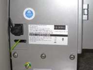
The potential equalization cable [cos10223] must be connected with the connector on the device plug and with the potential-compensation- bearing within the medically used room. During installation, connecting or disconnecting the potential equalization, the device (unweighting device) must not be connected to the power supply. Protection against electric shock has to be provided in the finished product/device
N When used in the medical field, all devices within the system have to be connected via a potential-compensation-cable in „star-connection“ with the potential-compensation- bearing within the medically used room.
N First connect the potential compensation (potential equalization) with the corresponding plug pin (next to the main switch at the front) and then connect the mains plug.
N During electric safety measurements and test (leakage currents, etc.) the potential
[5.E] Starting the unweighting device
[5.E1] Switching the device on

No. | Illustration | Description |
[01] |
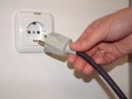
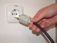
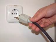
| Plug in the power supply of the h/p/cosmos airwalk se unweighting device into the dedicated socket. |
N The invervalls of switching Off- and On must not be shorter than 1-2 minutes. Otherwise it could lead to interference in the adjustment of the motor of the unweighting device or to the failure of the backup.
N The system should be unplugged in case of longer breaks (for example over night) .
[5.E2] Switching the device off

[5.F] Installation, Overview, Checklist
The authorized technician (distributor or service partner) has to check whether the installation of the device has been performed properly, before the customer is introduced into the operation of the h/p/cosmos device. For detailed information and instructions for installation and commissioning please refer to all respective individual chapters in this manual. Among others, following points save to be performed or controlled:
No. | Illustration | Discription |
[01] |
| Compare the delivery note with the installed unweighting device. Are all parts like unweighting bar, rope, machine folder and accessories complete and without damage. accomplished |
[02] |
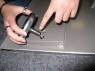
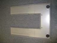
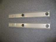
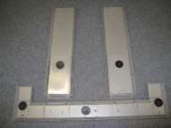
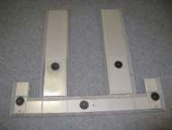
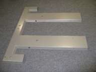
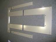
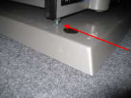
| After unpacking, lay components on a clean surface and screw in the levelling sockets according to the picture. screw in WITHOUT lock nut! DO NOT tighten the lock nut! accomplished |
[03] |
| After unpacking, lay components on a clean surface and screw in the levelling sockets according to the picture. accomplished |
[04] |
| After unpacking, lay components on a clean surface and screw in the levelling sockets according to the picture. accomplished |
[05] |
| After unpacking, lay components on a clean surface and screw in the levelling sockets according to the picture. Lay Components in right position for further assembling accomplished |
[06] |
| Connect parts with: 4 pcs. M8 x 30 8 pcs. NL8-Nord-Lock 4 pcs. nut M8 accomplished |
[07] |
| Turn around module for further assembling The module can now be placed on the future position of the system. accomplished |
[08] |
| Lay Components in right position for further assembling accomplished |
[09] |
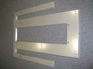
| Slide ground frame parts of the basic framework into each other and screw together. Screwing with 4 pcs. M8 x 16 panhead screws per side. If floor ist uneven, it can be compensated by the levelling sockets or the with the help of a screw driver (has to be removed afterwards). accomplished |
[10] |
| Slide frame parts for treadmill assembling into each other and adjust for the choosen h/p/cosmos running machine. see [11] Screw with 8 pcs. M8 x 16 panhead screws per side. If floor ist uneven, it can be compensated by the levelling sockets or the with the help of a screw driver (has to be removed afterwards). accomplished |
[11] | h/p/cosmos pulsar h/p/cosmos quasar h/p/cosmos mercury/locomotion
| |
[12] |
| Screw in all levelling sockets as far as they contact the floor and the thread bolts don´t endure the frames surface. Level the whole frame group with the levelling sockets: accomplished |
[13] |
| Straighten up left side arch, put it on the ground frame and screw it together with 8 pcs. M8 x 40 panhead screws. Until the arch is bolted up, an additional helper should secure it from falling accomplished |
[14] |
| Mount deflection pulley on right side arch: 4 pcs. M8 x 20 4 pcs. NL8-Nord-Lock
|
[15] |
| Mount deflection pulley on traverse: 4 pcs. M8 x 20 4 pcs. NL8-Nord-Lock
|
[16] |
| Straighten up right side arch, put it on the ground frame and screw it together with 8 pcs. M8 x 40 panhead screws. Until the arch is bolted up, an additional helper should secure it from falling accomplished |
[17] |
| Mount traverse with : 4 pcs. M16 x 35 4 pcs. NL16-Nord-Lock Tightening torque: 200Nm An additional worker ist needed. accomplished |
[18] |
| Mount block for Levi-unweighting unit. 3 panhead screws M8 x 16
|
[19] |
| Dismount the back board of Levi unweighting unit. Put it on block mounted under No. [18] and bolt it with: Ellen head screw 6 pcs. M8 x 16 included spring ring and lining disc. This operation must be done by two workers. Remount the back board after fixation of the Levi-Unit. Fix the potential equalisation cable on the back board! accomplished |
[20] |
| Connect the led outside potential isolation wire with the potential isolation bolt on the right side arch. accomplished |
[21] |
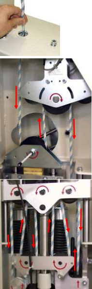
| Thread the rope in pulleys and guidances of the unweighting device. This procedure ist identical with the initial installation and with later rope changings: 1. Thread the rope through the top pulley: the rope must be inserted between the pulley and the marked bolt. |
hinten
vorne
|
accomplished | |||||
[22] | | | Wind the rope around the pulleys ( - ) in the unweighting unit. accomplished | |||
[23] | | | | CAUTION: The rope must be inserted between the pulleys and the guiding bolts!
accomplished | ||
| | |||||
| ||||||
[24] |
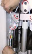
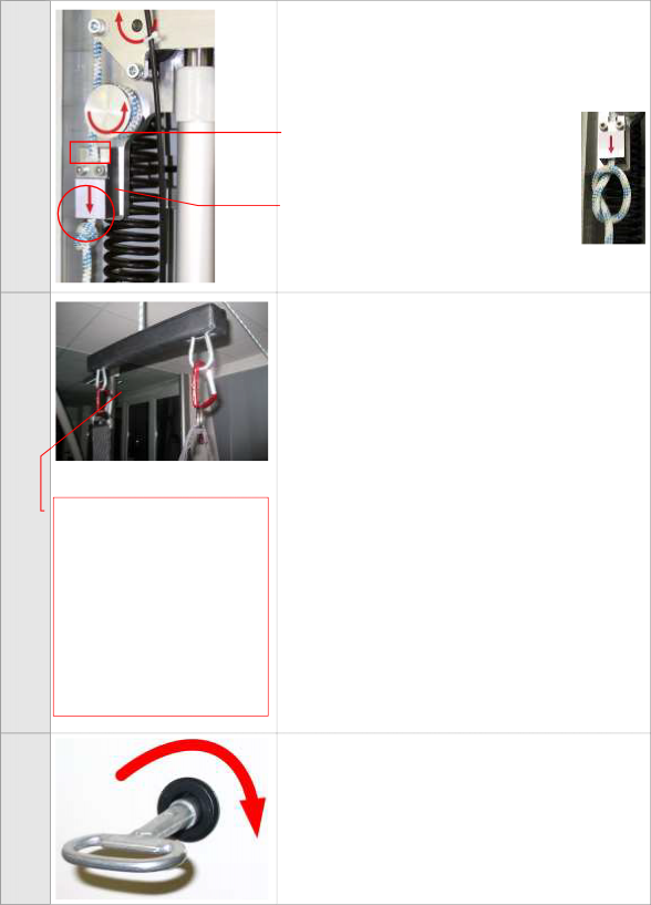
| Wind the rope around the rope drum (2 complete turns) Feed the rope through the rope fastening Fix the rope temporarily by slightly tightening both screws (you should still be able to move the rope) Rope drum Rope fastening with 2 screws accomplished |
[25] |
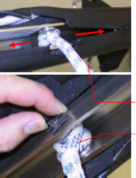
| Attach the support bar This step is not necessary within the first delivery, because it´s premounted by the producer. For later services, rope changes and maintenance-/cleaning jobs release the rope form the support bar and feed it in again. Open zippers You can easily undo the rope thimble´s locking device using your fingers an then remove the shaft. accomplished |
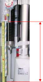
[26] | Residual length | How to set correct hight for the support bar: Push/pull the rope downwards through the rope fastening and measure the appropriate rope length as follows: Residual lenght with standard traverse: 121 cm
|
[27]
Fix and knot the rope:
Fix the rope by tightening both screws firmly until the clamping plate makes full contact.
Knot the rope as shown below and then tighten the knot.
Safety knot
Rope fastening
and clamping plate
The knot must be as close as possile to the rope fastening.
[28]
Raising a person with a body weight of approx. 80 kg:
The support bar can be raised to within 2 cm of the pulley.
CAUTION:
Before releasing the support bar, lower the person down to an appropriate height.
accomplished
Check for correct rope guidance and carry out a functional test: Run through the Levi’s entire range of motion with a load (person) attached using the remote control, monitoring the rope’s movement, especially in the Levi housing.
NOTE:
Once the height of the support bar has been adjusted (task 10), a patient with a body weight of 80 kg can be raised until the support bar is approx. 2 cm below the pulley.
Be aware that, if the patient lift is at its maximum position, the support bar can be pulled against the pulley with a maximum of 80 kg at lighter weights or if the dynamic range of motion is entered. This may damage the cushion of the support bar.
For this reason, ensure that the support bar is not pulled against the pulley.
In this case, correct the residual lenght as shown in [25] und [26]!
accomplished
[29]
Lock the housing of the Levi unit using the key.
accomplished

[30] |
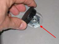
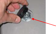
| Screw locking nut (arrow) on thread of the levelling sockets with a socket wrench size 24. Put on the cap afterwards. accomplished |
[31] |
| Check the wall socket: Optical check for damages, burned contacts, proper fixation and good ground contact (no paint, dirt, deformation) Check out the correct pin assignment of the wall socket with a socket-tester with direct indication. Check the electrical connection of the device: Direct connection to the wall socket with separate fuse, no danger of stumbling, no extension cable, no multiple plug socket, separate circuit for the treadmill. If a correct connection to the wall socket is not possible, note this on the delivery note, inform the customer and put the device out of operation (if necessary) and safe against start-up. accomplished |
[32] |
| Immediately at first installation an electric safety test / measurment has to be performed for „Protective Earth Resistance“, „Isolation Resistance“ and „Leakage Current“ and the values have to be recorded on a special protocol [cos11690xx] and marked with „first measured values“. For details please refer to chapter „maintenance / inspections“. One copy of this protocol [cos11690xx] remains at the owner’s manual and the original with the „first measured values“ shall be sent to h/p/cosmos. The potential equalization cable has to be connected AFTER the measurements. accomplished |
[33] |
| In case of using the h/p/cosmos airwalk se with h/p/cosmos running machine the running machine has to be set on the ground frame of the unweighting device, the plates of the rear sockets have to be dismounted and set into the fixings of the ground frame, that fit to the treadmill model. treadmills from other manufacturrers: only if authororized by angency confirmation! accomplished |
[34] |
| mounting the wheelchair ramp according to separate discription. For example h/p/cosmos locomotion med (option) accomplished |
[6.]Operation
[6thA] Controlelements and displays: Manual control unit and housing unweighting unit.
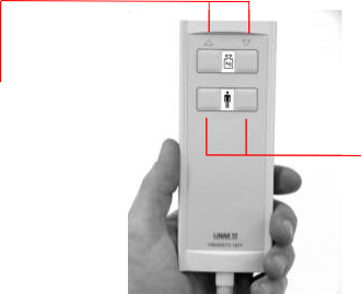
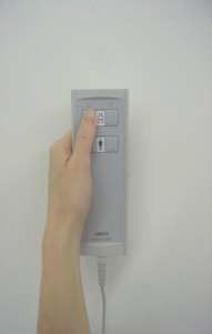
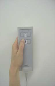
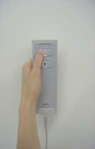
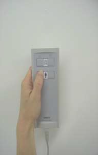
buttons fort he patient elevator (raising/lowering) and for adjusting the range of motion
[6thA1] Manual control unit of Levi unweighting unit
| Do not over strech spiral cable. Tap buttons only slightly. The keystroke is confirmed by a noticeable easing. |
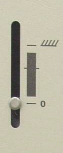
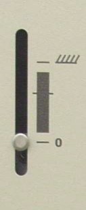
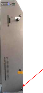
[6thA2] Displays of the Levi unweighting unit and the connection for manual control
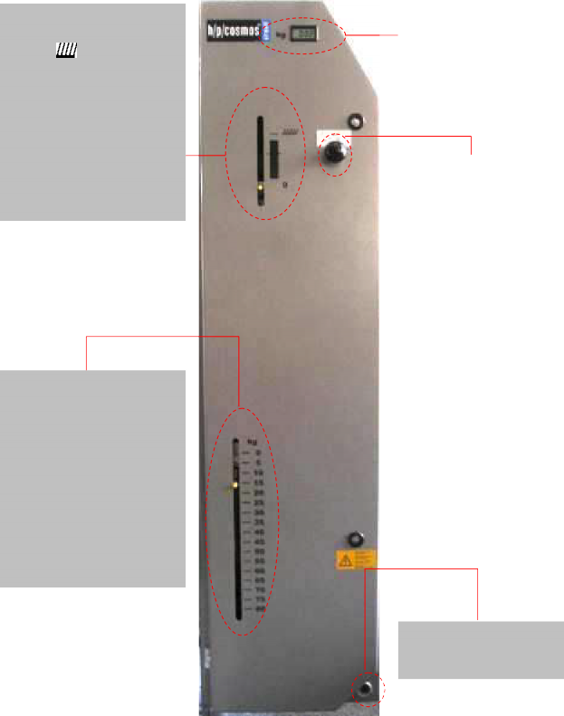
See page 10 – [9.C]
Position 0: No support
Position : Full support (patient scales indicate the patient’s weight)
The gray area marks the range of motion. If the pointer is in this area the patient is continually supported by the selected weight. You can use two buttons on the remote control unit to set the range of motion (see [5.A1]). Press and hold the relevant button down until the arrow appears in the desired range.
Indicates the patient’s weight (static mode) or the support weight at a given time (dynamic mode) in kilograms.
The displays consist of 2 mechanical scales and a digital LCD display
You can use two buttons on the remote control unit to set the weight support. Press and hold the relevant button down (see [5.A1]) until the pointer indicates the desired support weight.
(see [5.A1])
[7.]Training
[7.A] General notes
[7.A1] Suitable clothing
Wearing appropriate clothing can reduce the patient’s risk of skin irritation and lesions. We suggest patients wear tight-fitting pants made of soft cotton. Clothes made of thick, rough, fabrics with thick seams or very loose pants are unsuitable. Synthetic materials can cause mild burns on the skin due to friction.
Patients should wear flat, closed shoes on the treadmill. Where orthoses or, for instance, raised heels are required, suitable shoes must be worn to ensure a regular gait pattern.
| You can find further safety instructins in the front part of this manual. Please always pay attention on these instuctions. |
| If users have long hair there is a danger of their hair getting caught in the treadmill during treatment. For this reason, we recommend that long hair is kept tied up at all times using a hairnet or other means. |
[7.A2] Verwendete Laufbänder und Rollstuhlrampen:
Please always notice in case of using the h/p/cosmos airwalk se in conjunction with a treadmill the safety- and using instructions of the treadmill.
[7.A3] Before starting training
You must explain in detail to patients about what the Andago does before their first training session. Make patients aware of the benefits and risks of training.
[7.B] h/p/cosmos airwalk Vests
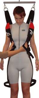
There will be supplied a unweighting vest with the h/p/cosmos airwalk se in standardconfiguration
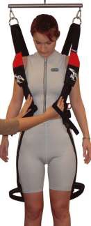
[7.B1] Putting on the Vest
Note:
Before putting the h/p/cosmos airwalk vest on, make sure the patient is wearing appropriate clothing. Loose fitting and slick clothing will tend to allow vest to ride up.
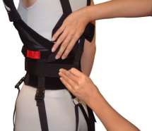
When putting on the vest, remember that a tight fit provides greater support and feels more comfortable when unweighted. Avoid pressure under the arms and around the legs. The vest must support the person from the waist, not from the arms, ribs or hips. Always fasten the straps in the order given in these instructions. In the following steps the terms left and right refer to the left and right of the person wearing the vest. All straps should be fully extended and adjusted later to fit.
[7.B2] Sizes
Size | Waist Size | Vest Color | Order number |
Small | 56 to 81 cm (<22 to 32 in) | red | cos10095 |
Medium | 81 to 112 cm (32 to 44 in) | blue | cos10096 |
Large | 112 to 140 cm (44 to 55 in) | yellow | cos10097 |
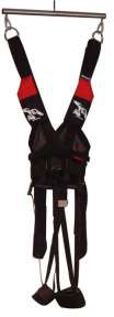
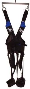
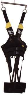
[7.B3] Adjust Chest Straps
Put the left side of the cross over chest strap through the d-ring on the inside right of the belt, pull back and attach to the Velcro. Pull the right side of the cross over chest strap tightly over to the right, through the d-ring and press down securely on the Velcro. The shoulder straps will remain loose until connected to the unweighting bar.
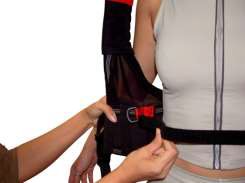
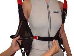
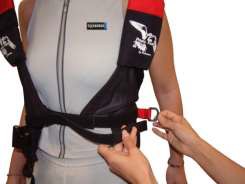
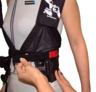
The cross over chest strap is a positioning strap: it will fit differently on different body types. It should be tight enough to hold the chest in place while strapping the waist, but not tight enough to restrict breathing. You may need to make several adjustments to position the strap correctly for each person: with women, for example, the strap should be just below the breast because Unweighting will raise the vest up so that the four-way stretch fabric will protect and support the bust. Make sure that the back D-ring is at the center back in alignment with the spine.
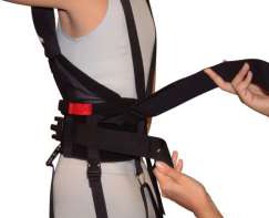
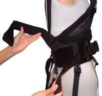
[7.B4] Buckle Waist
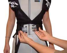
Buckle up both buckles. Tighten up the top buckle by pulling first on one side of the adjusting strap and then the other, keeping the buckle centered. Tighten up the second buckle using the same method. You may have to reposition the cross over strap and the first buckle to get a snug fit. Do not tighten enough to restrict breathing. Make sure that the back D-ring is at the center back in alignment with the spine.
N Note:
N The small (red) vest has only one waistband buckle, the medium (blue) and the large (yellow) have two.
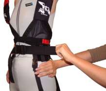
[7.B5] Cuff Leg
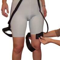
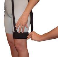
Leg straps should be all the way out. Each leg strap has a long front strap that attaches to the two adjustable buckles. On the vest fronts set the strap to the inside buckles for a small person and to the outside buckles for a larger person. The front strap should be centered from the waistband through the cuff, with the strap on the cuff in the center front of the thigh. The bottom of the leg cuff is set approximately 5 cm above the patella (knee). While holding the cuff in place (just above the knee), wrap the cuff and strap behind the leg then between the legs keeping the cuff taut. Pull on the strap to tighten comfortably. Press down on the Velcro to secure the strap. Repeat the procedure for the right leg.
[7.B6] Adjust Leg Straps
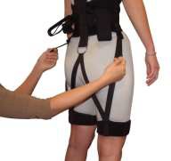
The back leg strap should be in a W position. Tighten the back leg straps by alternately pulling down on the adjustment straps attached to the side buckles. Do not tighten so much as to impede the normal leg action. The front leg straps are adjusted by pulling down on the buckle straps. It is not necessary to have the front straps snug. If the leg cuff rides up too much, reposition and retighten the cuff. Try to keep the front strap in the center of the thigh.
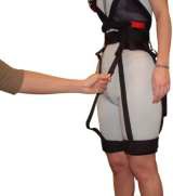
[7thC] Attaching the Vest to the Unweighting Bar
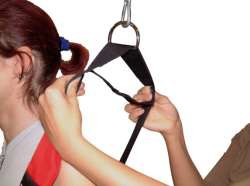
Each shoulder strap at the vest has a D-ring that attaches with karabiners to the unweighting bar. Adjust the upright posture of the patient by moving the D-ring back or forth on the straps. With this individual adjustment the patient can be prevented of falling over to the front or the back. Open the Velcro strap underneath the D-ring and adjust it. by moving forth or back. Close the Velcro.
The most important thing is, that the patient is feeling comfortable. Be sure that the vest is not wedged into the underarms and that it does not restrict breathing. Be sure that the leg straps are not tight enough to restrict circulation in the legs. Readjust the vest and single straps as necessary.
[7.C1] Correcting Vest Problems
If the vest rides up under the arms, reweight and pull the vest down. Have the person tighten the abdominal muscles, then retighten the waist straps and leg straps. If the chest strap is too tight during exercising, it has to be loosened. If the leg cuffs ride up, the cuff has to be fixed due to placing the front leg strap in the center of the thigh.
[7.D] Velcro-Gait Control Straps
The innovative gait control straps are found on the back of the h/p/cosmos airwalk vest. These elastic Velcro straps offer gait enhancement abilities never before obtained with traditional treatment. Helping to control internal/external foot rotation, stride length and hip rotation are just a few of the capabilities of the p/cosmos airwalk vest.
Some problems during the starting adjustments and some problems with the gait-belt are the internal or external foot rotation or an excessive stride length.
[7thD1] Internal Foot Rotation, Excessive Stride Length
The gait straps are attached to the plastic slides straight down and Velcroed to the back of the leg cuff. This helps to bring the foot into the proper position for correct stride.
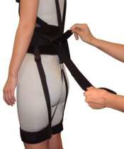
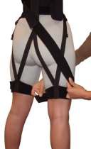
[7.D2] External Foot rotation
The gait straps are Velcroed to the front of the vest across the buttock, onto the top of the opposite thigh and attached to the leg cuff.
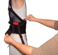
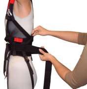
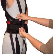
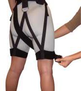
This helps to correct the external rotation of the foot/hip. The gait control straps are also used in the rehabilitation of stroke and patients with Neuro muscular problems. They can be used to increase the stride length.
[7thE] Putting on the h/p/cosmos airwalk Vest for Wheelchair Patients
N Put the left side of the cross over chest strap through the d-ring on the inside right of the belt, pull back and attach to the Velcro. Pull the right side of the cross over chest strap tightly over to the right, through the d-ring and press down securely on the Velcro.
N While holding the cuff in place (just above the knee), wrap the cuff and strap behind the leg then between the legs keeping the cuff taut. Pull on the strap to tighten comfortably. Press down on the Velcro to secure the strap. Repeat the procedure for the right leg. The front strap on the cuff should be centered on the thigh.
N Buckle up both buckles. Tighten up the top buckle by pulling first on one side of the adjusting strap and then the other, keeping the buckle centered. Next tighten up the second buckle using the same method. You may have to reposition the cross over strap and the first buckle to get a snug tight fit. Do not tighten enough to restrict breathing. Make sure that the back D-ring is at the center back in alignment with the spine.
Reposition leg straps if necessary after waist has been strapped. The shoulder straps will remain loose until connected to the unweighting bar.
The patient is now ready to be Unweighted. Before Unweighting anyone, be sure the waist belt is snug and that the safety snaps are closed completely.
N Place the wheelchair under the h/p/cosmos airwalk. For treadmills, you may need to use a ramp to place the person under the system.
N Pull the bar down and connect the extension with the karabiners to the unweighting bar.
N Unweight the person from the chair and remove the chair. Adjust the extension as needed.
Most of the comfort problems encountered during unweighting are the results of improper adjustment of the vest.
[7thF] Entering the unweighting device – supportign weight / standing up
N Move the patient in his wheelchair onto the treadmill below the support bar.
N Check that all the buckles on the unweighting vest are fastened securely.
N Check the rope for possible damage and ensure that it is in a good condition.

N Hook the support bar onto the eyelets on the unweighting vest (see Fig. 9) and lift the patient out of the wheelchair into a standing position by keeping the relevant button on the Levi remote control unit pressed down (see p34)
Before lifting up the patient the treadmill has to be in horizontal position! | |
Make sure before lifting the patient that the support weight set on the Levi system is definitely less than the patient’s weight! |
[7thG] Setting the support weight and range of motion
| Make sure that the patient’s wheelchair is located outside the 2-meter safety zone and that it cannot accidentally roll away. |
[01] |
| Set the support weight you want by pressing the relevant buttons on the Levi remote control unit. NOTE: If you do not know the patient’s weight, first select a support weight that is definitely less than the patient’s estimated weight. The patient can then be fully supported by pressing the relevant button on the Levi remote control unit (indicator in the |
[02] |
| Now set the range of motion by pressing the relevant buttons on the Levi remote control unit. The patient is continually supported by the support weight previously selected only if the indicator lies in the gray area between 0 and Now start the training session. |
[03] |
| The support weight and range of motion can be adjusted at any time to suit the patient’s requirements, without stopping the training session. You do this by pressing the relevant buttons on the Levi remote control unit (siehe Abb. [03] / [04]) Note: If only small adjustments need to be made, just touch the buttons without keeping them pressed down. |
[7.H] General advice for training
The user should find these instructions helpful when providing treadmill therapy manually. Apart from drawing on the literature published on this subject, these instructions are also mainly based on the experiences of physiotherapists. This series of instructions is obviously not exhaustive.
When receiving manual treadmill therapy, patients should carry out as many activities on their own as is medically sensible, making the best possible use of their remaining functions. The following principle should be applied in order to ensure this happens: depending on the patient’s training status, provide him with as little assistance and only support as much weight as is medically indicated. The purpose of the treatment is to achieve regular, symmetrical movement in both legs.
The following points in particular must be borne in mind during training:
| Ask patient how he is feeling in regular intervals Stop training session if the patient does not feel well. |
| Have the straps on the unweighting vest became loose? Stop the training session and retighten any loose straps on the unweighting vest. Check to see whether the straps and buckles are twisted. |
| Have the unweighting vest´s buckles opened? Stop the training session and close the open buckles. Check that the buckles are still intact. If you do not detect any defects you can continue training. The training session must be ended if any buckles are defective. |
[7.I] Unweighting / weight support
In order to achieve optimum activity from the patient’s leg muscles during treadmill training, the level of body weight support provided should not exceed 30-40% of the patient’s own body weight, provided this is not contraindicated by any other medical factors. In terms of the clinical factor you should use to determine the optimum body weight support, we recommend the point where the leg is sufficiently stabilized during the stance phase. You should bear in mind during the course of the training that the weight support must be reduced as quickly as possible according to the patient’s training status.
[7.J] speed
The decision as to which speed should be used during the training session depends on the patient’s abilities. In general, the increase in the speed of movements should be adapted individually to the progress the patient is making during treatment.
Selecting treadmill speeds that are deliberately slow may be beneficial to patients when they are learning or relearning to walk, especially at the start of treatment. In particular, being able to achieve a more effective and also more deliberate control of their movement can have a positive impact.
[7.K] Elevation
In order to provide sufficient variation as the treatment progresses, training can involve walking uphill (see picture).
| Please notice: N Start the training always in horizontal position of the treadmill N By changing the gradient angle you have to readjust the dynamic body weight support. |
[7.L] Trainingduration/ distance und training frequency
Training duration and distance are determined by the patient’s physical ability. We recommend short training sessions of 10-15 minutes to begin with, which can be adapted to the progress the patient is making during the course of treatment.
Current scientific knowledge about training stipulates as a requirement for maximum motor learning success that the organism has recovered as fully as possible (90-95% recovery) (Schnabel et al.(1997)). This is equivalent, for instance, to a rest period of 18 hours between two training sessions, which basically allows a training session every day using the h/p/cosmos airwalk se However, the decision about whether training can be carried out every day must always be made by the user, based on the requirements and abilities of the individual patient.
[7.M] Training troubleshooting
| Is there a person or object inside the danger zone? Stop the training session immediately and make sure that there is no other person or object inside the danger zone before restarting. |
| Do you notice the treadmill making jerky movements or unusual sounds? Stop the training session and carry out a functional check without a patient. Contact the treadmill producer. |
| The patient can not be lifted out of his wheelchair? Check that the selected support weight is less than the patient’s weight. If this is not the case, select a support weight that is definitely less than the patient’s weight. |
| The patient can not be lowered for technical reasons (winch and emergency release are no longer working)? Do not attempt to remove the patient from the device on your own. Ask for assistance from one or more people you have called upon, and they can lift the patient while you then undo the buckles on the unweighting vest. |
[7.N] After training
N Stop the treadmill.
N Push the wheelchair behind the patient.
N Lower the patient into the wheelchair by pressing the relevant button on the Levi remote control unit.
N Before undoing the unweighting vest, make sure that the indicator for the range of motion is in the position 0.
N Move the patient in the wheelchair off the treadmill via the ramp. It is essential that the user is standing behind the patient to slow down the wheelchair on the ramp.
N Now loosen the belt straps and remove the unweighting vest from the patient.
N Remember to enter the training data and update the patient record after every training session.
[7thO] At the end of a training day
N Switch of the treadmill according to the manufacturers orders.
N Pull the plug out of the socket, to separate the unweighting device h/p/cosmos airwalk se from the current.
[7.P] Patient documentation
You are recommended to create a patient record which you can use to note for every training session and patient the date, size of the unweighting vest, patient’s weight, body weight support, the walking distance, speed, as well as any other comments and observations on each training session.
[7.Q] Patient becomes unconscious
| A patient may have difficulties with circulation control when standing up from a seated position due to reduced muscle activity and paralysis of the vegetative nervous system. If the patient suddenly becomes unconscious the emergency physician must be informed and the patient laid down immediately or tilted backwards if sitting in a wheelchair. . |
[8.]Maintenance and safety inspections
The h/p/cosmos authorised service engineers are happy to help you in the case of occurring problems.
A preventive maintenance can avoid problems in the future and is indispensable for the safety of such technical devices. Therefore ask for an annual preventive maintenance contract, which is highly recommended by the manufacturer, from our service department. Some basic regular maintenance and regular safety checks are obligatory!
A therapy system can only be safe ir it is maintained on a regular basis and according to specified instructions
Maintenance must usually be carried out by h/p/cosmos or other by h/p/cosmos authorized persons every 12 months. Some preventive checks must also be carried out at shorter intervals.
N You are not permitted to use the h/p/cosmos airwalk se if it is more than 12 months since the last maintenance inspection.
N In case of any detected and/or assumed malfunctions and/or defects and/or unreadable safety warning labels the device has to be taken out of operation, the device has to be marked and secured against operation and the supplier and authorized service personnel has to be informed in writing.
N Disregard of warnings, disregard of intended and forbidden use, safety precautions and also unauthorized or lack of maintenance and/or regular safety checks may lead to injuries or death and/or can damage the device and will result in loss of any liability and warranty.
N Before intervening in the device for safety reasons switch the unweighting device off and pull the mains plug out.
N During all maintenance works and safety tests make sure that no third parties are directly or indirectly in contact with the device under test and/or the technician performing the test. Keep a

[8.A] Preventiv maintenance
Before switching the device on always check the circuit cable, plug, outlet socket and circuit entry of the device.
[8.B] Immediate maintenance
Immediate maintenance is necessary if:
N the device has been under high mechanical stress (push, power supply cable and/or interface cable defect through driving over it or pulling it)
N fluid has got into the device
N cable and/or connector plug have been damaged (therefore unplug cable from device and replace it)
N coverings and/or safety warnings have fallen off
N The rope or the deflection pulleys show sign of wear
N a defekt or malfunction of the device has been detected or is suspected
Only a properly and regularly serviced device is safe. The maintenance of the devices has to be performed by the service engineers authorized by h/p/cosmos, preferrably within the scope of a maintenance contract.
[8.C] Regular inspections/examinations

For use in sports and medical areas as well as for private, public and military applications refer to the date at the inspection sticker at your device.
To keep the condition of the device in due order, examinations have to be performed repeatedly. Follow manufacturers guidelines!
For the unweighting device h/p/cosmos airwalk se a maintenance interval respectively technical safety checks (STK) of one year (12 months) has been set.
These examinations are only to be performed by trained and authorized electric technicians.
The main inspection sticker on the device certifies also the inspection of the optional equipment and the accessories. However, inspection intervals for optional equipment and accessories (e.g. rope of h/p/cosmos airwalk unweighting device, chest belt for safety harness, compressors, etc.) can deviate significantly from inspection intervals of the main device. Read respective manuals for details.
For maintening the h/p/cosmos airwalk se there is a spezific detailed instruction and protocol form available.
[8thC1] Visual inspection dirt / damage – daily before training
N Carry out a general visual inspection to check for any damage to the treadmill and support system (particularly the rope). If any damage is suspected the h/p/cosmos airwalk se must not be used.
N Carry out a check for dirt, especially on the harnesses, leg straps, padding and Velcro fasteners and treadmill ramp (slipping hazard!). Dirty orthopedic components should be washed.
N Check the stitching and catches on the harnesses and leg straps. Defective orthopedic components must be replaced.
[8thC2] Emergency release unweighting device – every 3 months
N Functional test (enter in the “Maintenance activities report”).
N Lift up a weight or a person of a standard weight (e.g. 70 kg).
N Release the weight/person making several “interim” stops using the emergency release (see Part [3.C] of this manual).It must be possible to release the weight/person in a controlled manner. When the knob is released, the weight must be stopped again.
[8thC3] Running machine – follow manufacturers guidelines
N Maintenence according to the manufacturers guidelines.
[8thC4] Changing the rope – min. every year
The rope must be changed once a year (every 12 months). This ist one of the most important safety measure of all. [spare part: cos100320]
Changing the rope is only alowed to h/p/cosmos authorized technicians!
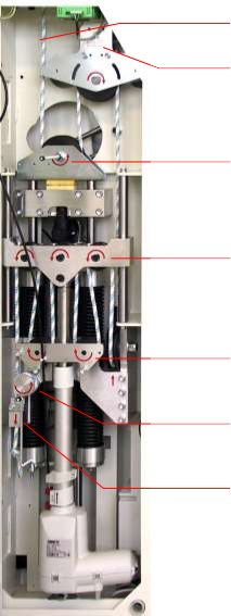
Figure Levi unweighting unit
At the beginnig of the rop – changing loosen the screws of the rope fastening and undo or cut off any knots at the end of the rope.
Pull rope out of the weight support pulleys.
Remove rope completely from the pulleys
Remove rope from support bar – see [4.E] – No. [24]
Afterwards thread the new rope into the unweighting unit according to [4.E] – startin at No. [20].
[8thC5] Spare parts
pos. | article description | units per machine | article code |
1. | Levelling socket h/p/cosmos airwalk se | 11 | cos100313 |
2. | Hexagon nut M16 DIN936 flat nut | 11 | cos100616 |
3. | circlip NL8-Nord-Lock | 4 | cos100308 |
4. | Button head socket screw M8x16 A2 | 16 | cos12634 |
5. | Button head socket screw, M8x40 V2A | 16 | cos11100 |
6. | pulley bottom side | 1 | cos100319 |
7. | pulley top side | 1 | cos100318 |
8. | mains cable 5m | 1 | cos100037va10 |
9. | Un-weighting rope - 7m - Ø8mm | 1 | cos100320 |
10. | snap hook with catch | 2 | cos11687-01 |
11. | discharge frame without hangers | 1 | cos100566 |
12. | Plastic cover plastic d=30mm, black | 7 | cos10535 |
13. | Cover cap plastic d=38mm black | 12 | cos10536 |
14. | cover cap plastik 60x60x3mm, black | 8 | cos100365 |
15. | Vest Medium f. h/p/cosmos airwalk (blue) | 1 | cos10096-01 |
16. | Vest Large f. h/p/cosmos airwalk (yellow) (optional) | 1 | cos10097-01 |
17. | Vest Small for h/p/cosmos airwalk (red) (optional) | 1 | cos10095-01 |
18. | Manual h/p/cosmos airwalk se EN | 1 | cos30017man-v1.3-en |
19. | key for controll desk levi | 1 | cos100642 |
[8thC6] Protective Earth Resistance RPE measurement
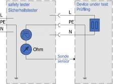
N Resistance between housing and ProtectiveEarth- Connection.
N The low resistance pass is to be controlled according to VDE 0701/0702 (sports and fitness machines) or VDE 0751/IEC 601-1 (medical devices) by the protective- resistance measurement with a measuring device for the protective-earth-resistance measurement.
N The connecting lead is to be moved while measuring for at least 5 sec. If the resistance changes hereby it is highly probable that the cable or the connectors have been damaged. In this case the cable has to be replaced and the device has to be repaired immediately.
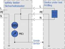
N Resitance between „briged“ L+N and ProtectiveEarth- Connection.
N Make sure that all isolations, that are under stress of the mains voltage, are being seized. All switches and contactors should be connected.
N The measuring is to be performed with measuring devices for the isolation-resistance measurement according to VDE 0701/0702 (sports and fitness machines) or VDE 0751/IEC 601-1 (medical devices).
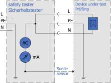
[8thC9] Electric Safety Tester an measurements
N Impedance measurement, indicating the current in the Protective¬Earth¬Cable
N The measuring is to be performed by a measuring device for leakage current measuring according to VDE 0701/0702 (sports and fitness machines) or VDE 0751/IEC 601-1 (medical devices).
N The measurement is equivalent to the single fault earth leakage current based on IEC 601.
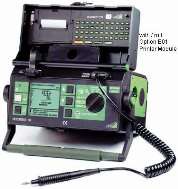
Picture: example for electric safety tester based on IEC601-1.
For all measurements read operation manuals of the measurement devices carefully and verify the values and intervals with the local guidelines and laws. An appropriate inspection record for all measurements and instructions are available at the manufacturers. See also detailed instruction and protocol form order no. [cos11690xx]. At first installation at the customer’s site and before first commissioning of the unweighting device device, the „first measured values“ have to be determined and recorded on a special protocol [cos11690xx] and marked with „first measured values“.
During each preventive maintenance and/or regular maintenance and/or also after each repair work on the device (even if it was only mechanical repair work!) all above mentioned electric safety measurements and checks (see protocol [cos11690xx]) have to be performed again. All values have to be compared with the „first measured values“ and allowed range of tolerance specified according to VDE 0701/0702 (sports and fitness machines) or VDE 0751/IEC 601-1 (medical devices).
In case any or more of the measured values is/are not within the allowed range of tolerance specified according to VDE 0701/0702 (sports and fitness machines) or VDE 0751/IEC 601-1 (medical devices), the device has to be repaired until the values are within the specified allowed range of tolerance. In case the device can not be repaired accordingly and immediately, the device has to be marked and secured against operation and the supplier and authorized service personnel has to be informed in writing.
[8thC10] Building installation: Electric Checks, Protective Earth Function, RCD, Leakage Current
The customer/operator has the operator duty to check the building installation (electrical installations and stationary installations) in regular intervals according to regulation BGV A3 of the professional association respectively information of legal accident insurance every 4 years, on their own response and expenses, for functions and safety of the complete electrical building installation. At operating sites or rooms of special function - such as e.g. climate chamber, pressure chamber, installation with special endangering, etc. - the interval is prescribed one year or shorter if applicable.
In any case use ground wire plugs with tested ground wires only. Existent earth leakage current protection switches (so called RCD or "residual-current-operated protective device") at the building installation must be tested by the customer/operator monthly (button at RCD switch in fuse box of the building installation) for correct and proper function. As a rule the RCD switches at the fuse box are labelled with "press monthly".
Normally a button at the RCD switch has to be pressed for testing (not the "main handle"). With that an earth leakage current is simulated. The RCD switch must then switch-off the complete electricity supply. These tests must be carried out by the customer/operator at a time, when the normal operation is not disturbed, all electrical devices and computers are switched off and nobody is endangered.
Due to the test of the RCD switch it possibly comes, depending on the circuit of the building electricity, to a switch- off of the complete or a part of the power supply of the building.
In this connection it is important to stress, that these are not regulations, standards and safety checks specifically for h/p/cosmos unweighting devices, but current regulations for all electrical devices and building installations worldwide and applicable for all electrical devices with metal housing.
[9.]Trouble shooting

[9.A] Mechanical / Noise problems
The h/p/cosmos airwalk se is an unweighting device with a spring mechanic. Ther may occure some noise during charging and discharging of the springs. If you perceive unusal noises:
N Check the mechanical device on overloading:
Have foreign objects (towels, cleaning cloths, etc.) come into the interior of the device?
N Check whether the noise comes from the treadmill.
If there ist no improvement, please contakt h/p/cosmos of your authorized h/p/cosmos dealer.
[9.B] Interference factor
[9.B1] Electrostatic Discharge
If the user moves around the devices they can be electro statically charged with up to several thousand volts. If then the user touches a metal piece, keys or display, it can lead to an electrostatic discharge between the user and the device. Electrostatic discharges can in certain cases result in an interference of the device. Generally those electrostatic discharges are without harm for the user as well as for the device, but can be quite unpleasant. The main causes for electrostatic discharges are the choice of clothes, the sole of a shoe and the movement. Very dry air and many light fittings can also lead to the same results.
Solution: Try different clothes or shoes, humidify the air in the room, and switch part of the light fittings off. Please inform the manufacturer if you detect such interference.
[9.B2] Source of Interference
The devices should not be installed near to e.g. an x-ray device, motors or transformer with high connection power, as the electric and magnetic interference can falsify measurements. Very strong sources of interference (e.g. above the limit according to EMT) can influence the functions of the device.
High-tension power lines nearby and electrical devices without c - sign and without a certificate of compliance for electro-magnetic-tolerance should be avoided as well.
Pay special attention to the EMC (electro magnetic compatibility) data and manufacturer’s declaration in the chapter „technical data / EMC“ of this manual.
[9thC] Voltage at the device housing / electric shock
[9thC1] Isolation from mains supply
In order to isolate the device from the mains supply unplug the mains cable from the socket or from the device.
[9thC2] Open (interrupted) earth wire / ground – shown here on the esample of a running machine
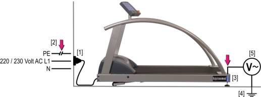
In case the earth wire (ground) is not connected (for example due to defect in the building installation), on the metal frame of the device a voltage will be life via the „Y-noise-suppression-capacity“. This characteristic is very common with almost all electrical equipment with metal housing and EMC-fault clearance filters. The earth wire and/or contactor at the wall socket [1] in the building or at any other part of the AC-power line/feeder is open [2]. In this case a voltage of approximately 110 volt runs via the capacitor, of the EMC-fault clearance filter (to be found in the device) between housing and earth. Via the capacitors of the incorporated EMC-filters a voltage [5] of approx. 110 volts AC is live between frame [3] and grounding [4], e.g. via the floor or heating radiator system or other grounded parts or machines.
If the device is flawless (at device category sports = without Potential-Isolation-Transformer) the current flow is significant noticeable in case of touching any bare metal parts (for example screws).
If the device is flawless (at device category medical = with Potential-Isolation-Transformer) the current flow is almost not noticeable in case of touching any bare metal parts (for example screws).

If the device is defective (at device category sports and also medical), e.g. because of a defective isolation inside the device, the current flow may be life-threatening high in case of touching any bare metal parts (for example screws).

Read and follow the directives and information concerning check of ground-wire terminals and functions in the chapters installation, maintenance and safety checks of this operation and service manual.
[9.D] Electrical interference
Interferences and error codes might be caused by problems with the power supply or because of not enough maintenance (e.g. pollution).
N Check voltage supply. Do not use extension cords or multi-way connectors. Connect the machine direct to the socket in the wall. Each machine should have an individual circuit.
N Check – if connected – the running machine
N Also contact problems at connectors (loose connections) caused by vibrations can result in malfunctions. So please check cables and connectors for loose connections.
[10.]Technical specifications
[10thA] h/p/cosmos airwalk se
h/p/cosmos airwalk se | |
Controls (Display & Keyboard) | 1 LCD display, 2 mechanical indicators, 4 keys, mechanical emergency release |
Power supply (standard, read nameplate) | 230 V ~ f: 50/60 Hz In case of use in conjunction with a running machine, an additional socket with the requirements oft he running machine is needed. |
Power input | 1840 VA |
Overvoltage category | Category II: Life-Earth < 300 V transient over-voltage limit 2500 V |
Fuse (standard, read nameplate) | 10 A |
Power consumption | max. 8 A |
Elevation motor capacity | 240 W |
Safety Standards | n IEC 60601-1, IEC 60601-1-1, IEC 60601-1-2, IEC 60601-1-6 DIN EN 12100-1, EN 957-1, DIN EN 62353, EN ISO 14971, ISO 9001, EN ISO 13485 |
Leakage current | 0.2 mA |
Isolation transformer | 1 x 100 VA |
Safety class / -categories | I / IP20 / B |
Mode of operation acc. IEC 60601-1 | Time of operation of 10% 2/18 = 2 minutes continuous use followed by 18 minutes not in use |
Field of operation / Accuracy | sports S I and medicine, accuracy ± 2 kg |
Classification according to MDD | II a |
Dimensions oft he h/p/cosmos airwalk se in different combinations with running machines: | ||||||
h/p/cosmos airwalk se without running machine | h/p/cosmos mercury med h/p/cosmos stratos med h/p/cosmos 150/50 locomotion DE med h/p/cosmos 150/50 locomotion force DE med | h/p/cosmos quasar med h/p/cosmos stellar med | h/p/cosmos pulsar | h/p/cosmos pulsar 3p | h/p/cosmos venus 200/75 (rs) if mounted in a pit | |
Required room height | 2670 mm standard – traverse 2980 mm high traverse for patiens up to 220 cm | |||||
Dimensions of frame length x width x height | 1960 x 2070 mm | 2230 x 2070 mm | 2430 x 2070 mm | 2630 x 2070 mm | 2630 x 2070 mm | 2420 x 2070 mm plus control unit |
Track access height from floor | ... | 240 mm | 280 mm | 280 mm | 280 mm | ... |
Weight of device | 275 kg | 600 kg | 780 kg | 810 kg | 850 kg | 1075 kg |
App. values, depending on the equipment of the running machine | ||||||
Weight load limits to floors (traffic load to DIN 1055 part 3) | 3.64 kN/m² | 3.90 kN/m² | 3.94 kN/m² | 3.69 kN/m² | 3.77 kN/m² | 4.58 kN/m² |
In case of any further questions related to load limits onto floors, please ask our service department. | ||||||
max. permissible user weight | 135 kg / 297 lbs | |||||
max. user height | 200 cm at standard equipped system system hight 267 cm (105.11“) with an elevation of more than 10% use may be limited by the running-machine model, the size of the patient and the kind of (sportive) exercise. An optional higher traverse is available for patients up to 220 cm. system hight with high traverse is app. 298 cm (117.32") | |||||
Dynamic body weight support | approx. 1...75 kg Due to manufacturing tolerances of the body weight support mechanism the maximum selectable support weight cannot exactly be named. However, the value of 75 kg can always be achieved.. | |||||
Operation range | 18 cm (vertical range of motion) at dynamic weight support. | |||||
Support weight graduation | continous | |||||
Unweighting indication (elektronic Display) | Resolution: 1/10 kg on patients scale/display oft he aktual weight support accuracy: app. ± 2 kg - Due to rope elasticity and friction of the rope pulleys (indirect measurement via pulleys) the weight measurement system has a relatively coarse hysteresis | |||||
Environmental conditions: Transport and storage | temperature: –20...+60 °C humidity: 20...90% - without condensation barometric pressure: 700...1060hPa | |||||
Environmental conditions: Operation | termperature: +10...+30 °C (deviation on request) humidity: 30...75% - without condensation barometrci pressure: 700...1060hPa Maximum operating altitude: approx. 10,000 feet (3000m), without pressurization | |||||
combinable h/p/cosmos running machines | h/p/cosmos mercury, h/p/cosmos locomotion, h/p/cosmos quasar, h/p/cosmos pulsar in their different version h/p/cosmos venus 200/75 in pit at ground level installation. | |||||
Ask for further details and optional equipment or visit www.h-p-cosmos.com. Subject to technical alterations without prior notice. E & EO.
[10thB] EMC electromagnetic compatibility. Guidance and manufacturer's declaration
Table 201: Guidance and manufacturer's declaration - electromagnetic emissions (for all equipment and systems) | ||
The unweighting device is intended for use in the electromagnetic environment specified below. The customer or the user of the unweighting device should assure that it is used in such an environment. | ||
Emissions test | Compliance | Electromagnetic environment — guidance |
RF emissions CISPR11 | Group 1 Class B | The unweighting device uses RF energy only for its internal function. Therefore, its RF emissions are low and are not very likely to cause any interference in nearby electronic equipment. |
RF emissions CISPR11 | Group 1 Class B | The unweighting device is suitable for use in all establishments including domestic and those directly connected to the public low-voltage power supply network that supplies buildings used for domestic purposes. |
Harmonic emissions IEC 61000-3-2 | Class A | |
Voltage fluctuations/ flicker emissions IEC 61000-3-3 | Complies | |
Table 202: Guidance and manufacturer's declaration - electromagnetic immunity (for all equipment and systems) | |||
The unweighting device is intended for use in the electromagnetic environment specified below. The customer or the user of the unweighting device should assure that it is used in such an environment. | |||
Immunity test | IEC 60601 test level | Compliance level | Electromagnetic environment - guidance |
Electrostatic discharge (ESD) IEC 61000-4-2 | ±6 kV contact ±8 kV air | ±6 kV contact ±8 kV air | Floors should be wood, concrete or ceramic tile. If floors are covered with synthetic material, the relative humidity should be at least 30 %. |
Electrical fast transient/burst IEC 61000-4-4 | ±2 kV for power supply lines ±1 kV for input/output lines | ±2 kV for power supply lines ±1 kV for input/output lines | Mains power quality should be that of a typical commercial or hospital environment. |
Surge IEC 61000-4-5 | ±1 kV differential mode ±2 kV common mode | ±1 kV differential mode ±2 kV common mode | Mains power quality should be that of a typical commercial or hospital environment. |
Voltage dips, short interruptions and voltage variations on power supply input lines IEC 61000-4-11 | <5 % UT (>95 % dip in UT) for 0.5 cycle | <5 % UT (>95 % dip in UT) for 0.5 cycle | Mains power quality should be that of a typical commercial or hospital environment. If the user of the unweighting device requires continued Operation during power mains interruptions, it is recommended that the unweighting device be powered from an uninterruptible power supply or a battery. Caution! unweighting devices require high capacity UPS because of high capacity motor drive. |
40 % UT (60 % dip in UT) for 5 cycles | 40 % UT (60 % dip in UT) for 5 cycles | ||
70 % UT (30 % dip in UT) for 25 cycles | 70 % UT (30 % dip in UT) for 25 cycles | ||
<5 % UT (>95 % dip in UT) for 5 sec | <5 % UT (>95 % dip in UT) for 5 sec | ||
Power frequency (50/60 Hz) magnetic field IEC 61000-4-8 | 3 A/m | Not applicable | Power frequency magnetic fields should be at levels characteristic of a typical location in a typical commercial or hospital environment. |
NOTE UT is the A.C. mains voltage prior to application of the test level. | |||
Please pay special attention also to the other EMC related chapters of this manual:
Chapter: Safety, Installation, Operation, POLAR heart rate monitor: EMC
Chapter: Error, Malfunction, possible interference
Table 204: Guidance and manufacturer's declaration -electromagnetic immunity (for all equipment and systems that are not life supporting) | |||
The unweighting device is intended for use in the electromagnetic environment specified below. The customer or the user of the unweighting device should assure that it is used in such an environment. | |||
Immunity test | IEC 60601 test level | Compliance level | Electromagnetic environment — guidance |
Portable and mobile RF communications equipment should be used no closer to any part of the unweighting device, including cables, than the recommended separation distance calculated from the equation applicable to the frequency of the transmitter. Recommended separation distance | |||
Conducted RF IEC 61000-4-6 | 3 Vrms 150 kHz to 80 MHz | 3 Vrms | d = 1.17 1/V * √P |
Radiated RF IEC 61000-4-3 | 3 V/m 80 MHz to 2.5 GHz | 3 V/m | d = 1.17 m/V * √P for 80 MHz to 800 MHz |
d = 2.33 m/V * √P for 800 MHz to 2.5 GHz where P is the maximum output power rating of the transmitter in watts (W) according to the transmitter manufacturer and d is the recommended separation distance in meters (m). Field strengths from fixed RF transmitters, as determined by an electromagnetic site survey, a should be less than the compliance level in each frequency range. b Interference may occur in the vicinity of equipment marked with the following symbol:
| |||
NOTE 1: At 80 MHz and 800 MHz, the higher frequency range applies. NOTE 2: These guidelines may not apply in all situations. Electromagnetic propagation is affected by absorption and reflection from structures, objects and people. | |||
a Field strengths from fixed transmitters, such as base stations for radio (cellular/cordless) telephones and land mobile radios, amateur radio, AM and FM radio broadcast and TV broadcast cannot be predicted theoretically with accuracy. To assess the electromagnetic environment due to fixed RF transmitters, an electromagnetic site survey should be considered, If the measured field strength in the location in which the unweighting device is used exceeds the applicable RF compliance level above, the unweighting device should be observed to verify normal operation. If abnormal performance is observed, additional measures may be necessary, such as reorienting or relocating the unweighting device. | |||
b Over the frequency range 150 kHz to 80 MHz, field strengths should be less than 3 V/m. | |||
Table 206: Recommended separation distances between portable and mobile RF communications equipment and the unweighting device (for all equipment and systems that are not life supporting) | |||
The unweighting device is intended for use in an electromagnetic environment in which radiated RF disturbances are controlled. The customer or the user of the unweighting device can help prevent electromagnetic interference by maintaining a minimum distance between portable and mobile RF communications equipment (transmitters) and the unweighting device as recommended below, according to the maximum output power of the communications equipment. | |||
Rated maximum output power of transmitter (in Watt) W | Separation distance (in meters) according to frequency of transmitter | ||
150 kHz to 80 MHz d = 1.17 1/V * √P | 80 MHz to 800 MHz d = 1.17 m/V * √P | 800 MHz to 2.5 GHz d = 2.33 m/V * √P | |
0.01 W | 0.12 m | 0.12 m | 0.23 m |
0.1 W | 0.37 m | 0.37 m | 0.74 m |
1 W | 1.17 m | 1.17 m | 2.33 m |
10 W | 3.70 m | 3.70 m | 7.37 m |
100 W | 11.7 m | 11.7 m | 23.3 m |
For transmitters rated at a maximum output power not listed above, the recommended separation distance d in meters (m) can be estimated using the equation applicable to the frequency of the transmitter, where P is the maximum output power rating of the transmitter in watts (W) according to the transmitter manufacturer. NOTE 1: At 80 MHz and 800 MHz, the separation distance for the higher frequency range applies. NOTE 2: These guidelines may not apply in all situations. Electromagnetic propagation is affected by absorption and reflection from structures, objects and people. | |||
[11.]accessories and options
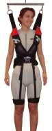
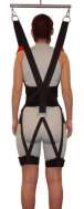
[11thA] Vests for subjects for h/p/cosmos airwalk and h/p/cosmos airwalk se
The vests offer high compatibility at best attainable freedom of body motion. They do not have undercutting straps during gait and have an optimum fitting due to the individually adjustable strap system.
4 different vests provide adaptation to all body sizes and forms. A special vest for children is also available. Additional straps for gait correction vest are included in the shipment. The unweighting is adjustable by the testing person itself.
h/p/cosmos airwalk vest red, waist 55-88 cm [cos10095] h/p/cosmos airwalk vest blue, waist 81-112 cm [cos10096] h/p/cosmos airwalk vest yellow, waist 112-145 cm [cos10097] h/p/cosmos airwalk vest children [cos10112]
[11.B] Wheelchair ramp
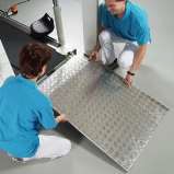
When using the wheelchair access ramp pay particular attention to the gap between ramp and running belt that hands, hair, clothing or other items do not get caught. The ramp should not touch the running belt as this will lead to excessive wear. Ensure that the ramp is stable and cannot slip. Be aware of danger of slipping or tripping on ramp. Do not attempt to mount ramp from the side. Only original h/p/cosmos wheelchair access ramps should be used.
wheelchair ramp 150/50 [cos16186]
[11.C] h/p/cosmos running machines
See page 4 of this manual.
For further details contact your authoriced h/p/cosmos dealer.
[11.D] Safety multiple socket
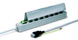
The stable safety multiple socket [cos100157] can be used for the safe connection of a medical h/p/cosmos treadmill with peripheral devices such as PCs, printer or monitors.
It meets all requirements for multiple sockets for creating connections of a medical electrical system within the patients environment.
safety multiple socket [cos100157]
As claimed in the norm EN60601-1 for medical electrical devices, the multiple socked is accessible only with the help of a tool. With this method an unintentionally made connection of further devices to the system is avoided, which lowers the risk of an exceedance of the maximum allowed patient-leakage-current of 0.5mA at the complete system.
[12.]Certificates
Certificates based on ISO 9001 and EN ISO 13485 and CE declaration of conformity see website: http://h-p-cosmos.com/en/safety/certificates.htm
[13.]Disposal
By request and at the expense of the client h/p/cosmos might take over the disposal of old devices and devices not longer functioning. Please contact service@h-p-cosmos.com for a detailed offer. Note the information for possible disposal of the unweighting device parts or components through the client or a subcontractor.

The h/p/cosmos devices are marked with following sign / symbol on the name plate:
Symbol for collection, treatment, recycling and disposal of waste electrical and electronic equipment (WEEE) as set out in Directive 2002/96/EC of January 27, 2003 of the European Parliament and of the Council on waste electrical and electronic equipment are necessary to reduce the waste management problems linked to the heavy metals concerned and the flame retardants concerned.
h/p/cosmos EAR WEEE-Reg.-No. DE 42594388
[13.A] Disassemble and cut up
Use personal protective equipment, when cutting up material of any kind with the appropriate tools (eye-protection, dust- mask, etc.). Contact service@h-p-cosmos to receive the safety-data-sheet according to European Commission Directive 91/155/EEC for a material.
[13thB] h/p/cosmos unweighting devices
h/p/cosmos running unweighting devices consist among other things of powder coated and galvanized metals from different producers and qualities, stainless steel parts, aluminium parts, plastics, rubber, electronics with cables, boards and condensers as well as batteries. These materials can be recycled by handing them to the official municipal valuable substance collection or to authorized disposal partners of valuable substance disposal. Pay attention to the regulations of the disposal company.
[14.]Contact
For additional orders and technical enquiries please have the model type, the serial number and the date of installation of your unweighting device ready. In case of any further questions about delivery dates, service or maintenance, orders for consumables etc., please contact the corresponding phone, fax or email for qualified help.
[14.A] Service department
phone | +49 86 69 86 42 0 |
phone direct | +49 86 69 86 42 25 |
fax | +49 86 69 86 42 49 |
[14.B] Sales department
phone +49 86 69 86 42 0
fax +49 86 69 86 42 49
[14.C] Headquaters
h/p/cosmos sports & medical gmbh Am Sportplatz 8
DE 83365 Nussdorf-Traunstein Germany
phone +49 18 05 16 76 67
fax +49 18 05 16 76 69
email@h-p-cosmos.com www.h-p-cosmos.com
Building 1 (top picture)
h/p/cosmos development & production Am Sportplatz 8
DE 83365 Nussdorf-Traunstein
Building 2 (picture below) h/p/cosmos sales & service Feldschneiderweg 5
DE 83365 Nussdorf-Traunstein
[15.]Appendix – Instruction and commissioning
Once the installation of the unweighting device has been completed, the h/p/cosmos employee / h/p/cosmos partner starts with the instruction and commissioning of the device. It is important to include all people in the instruction and commissioning, who are going to work with the unweighting device. After the instruction is completed the instruction protocol is to be signed by the h/p/cosmos technician and all trained persons and sent back, together with the signed delivery note and the registration form, to h/p/cosmos.
h/p/cosmos zurück gesendet werden.
[15.A] Calibrating the unweighting indications
Maintenance on medical products and electrical devices may only be performed by h/p/cosmos authorised and trained personnel
[01] |
| Calibrating the unweighting scales: A complete reset on „0“-kg is in cause of the construction of the device not possible. A rest weight of app. 0,3kg will always be displayed. Short-circuit terminal 10 (calibration) and terminal 15 (GND) with each other, using a piece of wire. The display will show the currently attached weight as 0 kg. Calibrating them with the support bar and unweighting vest attached: (note in the service list) accomplished |

[15.B] Instruction into general operation
N |
| Hand over directions for use. Inform about directions for use (always keep one within reach of all users). accomplished |
[01] |
| Refer to general warnings and safety precautions according to the directions for use. Place the print-out of the safety precautions (DIN A4 form in the delivery folder) close to the unweighting device. accomplished |
[02] |
| Especially point out the necessary safety-zone of min. L: 200 cm x W: 100 cm (or wider if running deck is wider) in case of fall. accomplished |
[15.C] Instruction into functions
[01] |
| How to switch the unweighting device on and off. accomplished |
[02] |
| How to set the support weight you want, by pressing the relevant buttons on the Levi remote control unit. NOTE: If you do not know the patient’s weight, first select a support weight that is definitely less than the patient’s estimated weight. The patient can then be fully supported by pressing the relevant button on the Levi remote control unit (indicator in the accomplished |
[03] |
| How to set the range of motion by pressing the relevant buttons on the Levi remote control unit. The patient is continually supported by the support weight previously selected only if the indicator lies in the gray area between 0 and Now start the training session. accomplished |
[04] |
| Show how the support weight and range of motion can be adjusted at any time to suit the patient’s requirements, without stopping the training session. You do this by pressing the relevant buttons on the Levi remote control unit (siehe Abb. [03] / [04]) Note: If only small adjustments need to be made, just touch the buttons without keeping them pressed down. |
[05] |
| Explain the Levi unweighting unit . accomplished Explain how to plug in the hand held remote control unit. accomplished |
[06] |
| Note the correct way to put on subject vest and connection to the support bar. See page 38 of this user-manuals.
accomplished |
[15thD] Instruction in maintenance works and safety checks
[01] |
| Advise the customer to do regular inspection of the rope and pulleys. The manufacturer recommends maintenance contract by authorized h / p / cosmos service technician. Not or poor or from unauthorized personal done maintenance work and / or repair work or technical security controls mean danger for man and machine, can cause defects and lead to extinction and loss of any liability an warranty by the manufacturer. accomplished |
[02] |
| Note to the Propper the adjustment of the levelling sockets. (in case of a later necessery adjustment) accomplished |
[03] |
| Note that the screw locking nut (arrow) has to be replaced afterwards on thread of the levelling sockets and tightened with a socket wrench size 24 again. Put on the cap afterwards again. accomplished |
[04] |
| Inform about the correct connection of the wheelchair famp if used. accomplished |
[05] |
| Inform about periodically recurring maintenance intervals and obligatory safety controls and the risks and dangers in case of disregarding these points. Offer and recommend maintenance contract through authorized and trained personnel. accomplished |
[15.E] Advice and support documents
[06] |
| Hand over and explain delivery papers (folder). Fill out registration form and send it to h/p/cosmos sales. Let the customer sign the delivery note and instruction protocol and send it back to h/p/cosmos sales immediately. Ask for brochure of customer and send it to the sales department at h/p/cosmos. accomplished |
[15thF]Confirmation of commissioning and introduction / instruction
By signing this protocol the authorised h/p/cosmos technician and the h/p/cosmos customer confirm the receipt and understanding of all warnings, safety precaution information, the performed instruction and commissioning according to form cos15228-01. The customer and user confirm the receipt of the listed devices including all accessories and options according to the h/p/cosmos delivery note. Disregard of warnings, disregard of intended and forbidden use, safety precautions and also unauthorized or lack of maintenance and/or regular safety checks may lead to injuries or even death and/or can damage the device and will result in loss of any liability and warranty. Please fill out the instruction protocol and send back to h/p/cosmos via Fax to +49 / 86 69 / 86 42 49, via email to sales@h-p-cosmos.com or via post
h/p/cosmos sports & medical gmbh Am Sportplatz 8 DE 83365 Nussdorf-Traunstein / Germany
customer’s (end-user’s) stamp / customer address:
h/p/cosmos device, model name | device serial number |
instructor | name in clear block letters | h/p/cosmos dealer / technician | date and signature |
instructed persons / customer / user / operator | name in clear block letters | position / function / department | date and user’s signature |

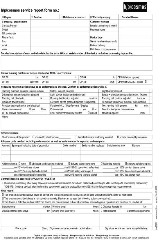
[15.G] Service report – cos15531

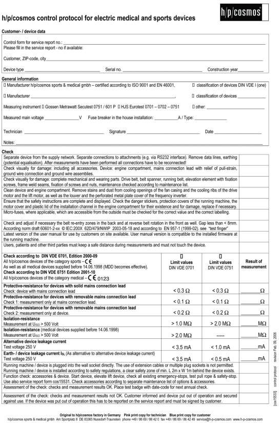
[15.H] Control protocol – cos15533
[15.I] Patients record | ||
Patients record for h/p/cosmos airwalk se | ||
Patient: | Month: | Year: |
Unweighting vest: | Weight: | Hospital: |
Date | Support kg] | Speed [km/h] | Distance [m] | Duration [min] | Comments | Sign |

Name (Technician): .......................................................
Serial-No. h/p/cosmos airwalk se: ......................................
Company /Distributor):.....................................................
........................
Date:
Device installed:
[15thJ] Protocol for maintenance on h/p/cosmos airwalk se
Date | Maintenance activities (based on page 51 section [7.C1]visual inspection section [7.C2] emergency release | Defects | Action to be taken (e.g.: rectify defect / notify h/p/cosmos distributor / order replacement) | Stamp / Signature |
no yes | ||||
no yes | ||||
no yes | ||||
no yes | ||||
no yes | ||||
no yes | ||||
no yes | ||||
no yes | ||||
no yes | ||||
no yes |
[15thK] Connection Diagram