
H-P-COSMOS Sports & Medical Ergometers
... and you'll run ahead of time!
file: L:\Manual\aktuell\H-P-COSMOS LB MCU 2 & 3\english\Manual H-P-COSMOS Treadmill MCU2 EPROM 2.31 + MCU3.doc
created: 06.02.2001 saved: 26.09.2001 printed: 12.10.2001 12:26 ha © 2001 - 2001 ! "
Author: ha cc:
Instruction-Manual
Service-Manual
Running-Machine
(Treadmill-Ergometer)
H-P-COSMOS® Types
MERCURY© (built 1994 – 1997) | c | MERCURY©med (built 1994 – 1997) c | ||
STELLAR© | c | STELLAR©med | n | |
QUASAR® | c | QUASAR®med | n | |
PULSAR® | n | VENUS© | n | |
SATURN® | n | ORBITER© | n | |
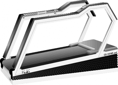
Development, Manufacturing and Distribution: H-P-COSMOS® Sports & Medical GmbH Sports. Medical. Science. Technology.
Am Sportplatz 8
DE 83365 Nussdorf-Traunstein / Germany Tel.: +49 - (0)8669 - 8642-0
Fax ISDN: +49 - (0)8669 - 8642-49
Edition: Version MCU 2 EPROM firmware Version: 2.31 dated 02/2001
Edition: Version MCU 3 EPROM firmware Version: 2.310 dated 07/2001
Printed: 12.10.2001
file: L:\Manual\aktuell\H-P-COSMOS LB MCU 2 & 3\english\Manual H-P-COSMOS Treadmill MCU2 EPROM 2.31 + MCU3.doc created: 06.02.2001 saved: 26.09.2001 printed: 12.10.2001 12:26 ha © 2001 - 2001 ! " author: HA cc:

Certificate of Compliance
for Sports- & Fitness Machines
Manufacturer:
H-P-COSMOS® Sportgeräte GmbH
Treadmill-Ergometer for Sports, Rehab & Science Am Sportplatz 8
D – 83365 Nussdorf-Traunstein / Germany Tel. ISDN Sales: ++49 / 1805 / 167667
Tel. ISDN Service: ++49 / 1805 / 167668
Fax ISDN: ++49 / 1805 / 167669
eMail: Sales@H-P-COSMOS.com eMail: Service@H-P-COSMOS.com Internet: www.H-P-COSMOS.com
Product: Running-Machine (Treadmill-Ergometer)
Type H-P-COSMOS: STRATOS© LT, MERCURY© LT, STRATOS© NT, MERCURY©, STELLAR©, QUASAR®, VENUS© 200-75 LT S
We herewith declare that the above mentioned products meet the following standards:
EN 60335 – 1
EN 957 / 1
EN 957 / 2
EN 957 / 6
VDE 0100 / 0113
VDE 0701
ISO 9001
DIN 32933
The c -mark gets affixed to the products according to appendix I of the EC-Council- Directive 89/336/EEC (Electromagnetic compatibility).
Nussdorf / Traunstein, 03.02.2000


Franz Harrer
President
Ludwig Fritzenwenger
Safety Representative for Medical Devices
file: L:\Manual\aktuell\H-P-COSMOS LB MCU 2 & 3\english\Manual H-P-COSMOS Treadmill MCU2 EPROM 2.31 + MCU3.doc created: 06.02.2001 saved: 26.09.2001 printed: 12.10.2001 12:26 © 2001 - 2001 ! "
author: HA cc:

Certificate of Compliance
for Medical Devices
Manufacturer:
H-P-COSMOS® Sportgeräte GmbH
Treadmill-Ergometer for Sports, Rehab & Science Am Sportplatz 8
D – 83365 Nussdorf-Traunstein / Germany Tel. ISDN Sales: ++49 / 1805 / 167667
Tel. ISDN Service: ++49 / 1805 / 167668
Fax ISDN: ++49 / 1805 / 167669
eMail: Sales@H-P-COSMOS.com eMail: Service@H-P-COSMOS.com Internet: www.H-P-COSMOS.com
Product: Running-Machine (Treadmill-Ergometer)
Type H-P-COSMOS: STRATOS© LT med, MERCURY© LT med, STRATOS© NT med,
MERCURY© med, STELLAR© med, QUASAR® med, PULSAR®, VENUS©, SATURN®, ORBITER©
Classification according to GL 93/42 EEC: Class IIb
We herewith declare that the above mentioned products meet the provisions of the
EC Council Directive 93/42 EEC (Medical Device Directive)
The appendix II of the Directive 93/42 EEC from June 14, 1993 is being applicable. Following standards are applicable: EN 60601 – 1
EN 60601 – 1 – 2
EN 60601 – 1 – 4
EN 957 / 1
EN 957 / 2
EN 957 / 6
VDE 0100 / 0113
VDE 0751
ISO 9001
DIN 32933
Nussdorf / Traunstein, 03.02.2000


Franz Harrer
President
Ludwig Fritzenwenger
Safety Representative for Medical Devices
List of contents
Description Page
General Information 11
Danger Precautions 12
Technical data 13
Safety standards / Approvals 16
Mark of Conformity 16
VDE Norm 16
The c-Mark 16
The n-Mark 16
Field of Application 16
Professional Application in Sports and Fitness 16
Professional Application in the Medical Field 16
Forbidden Use 17
Transport, unpacking and Packaging 17
Moving the Machine to upper or lower Floors and through narrow Doors 17
Mechanical Installation 17
Electrical Installation 18
Operation 18
Switching the Device ON 18
Devices for Sports and Fitness 18
Devices for Medical Application 18
Switching the Device OFF 19
Devices for Sports and Fitness 19
Devices for Medical Application 19
The Emergency-Stop / Emergency-Off 19
UserTerminal and Display 19
The Keys 19
The Display 20
Mode of Operation: 21
Manual Mode / Basic Functions MCU 2 & MCU 3 21
.D Start Running-Machine 21
.C Maintain Speed 21
.A D Change Speed 21
10.1.3.1 Acceleration Table 21
.E F Change Elevation 22
.C Maintain Elevation 22
.A Pause 22
.G STOP - End Running 22
Automatic Mode / Special Functions 22
.1 Call up (start) a Program/Profile 22
Program Overview for MCU 2 and MCU 3 23
Fixed Programs models without elevation 23
Fixed Programs models with elevation 23
Test Programs models with elevation 23
User Profiles 25
.2 Enter Program / User-Profiles 25
Program Memory Locations 25
Parameter Input per Program Step 25
Select Memory Location 25
Programming 25
Acceleration Level 26
Speed 26
Duration - Time 26
Distance > Length 26
Pause 26
End of Program, Saving 26
Program Correction, Program Modifications 26
Delete Program 27
Programming Examples for MCU 2 and MCU 3 27
.3 Preselection of Speed 28
.4 Sprint Programming: Acceleration up to max. Speed 28
.5 Selection of Display / Display Scrolling 28
.6 Entry of the Subject's Body Weight 28
.7 Heart-Rate-Dependent Exercise Control (Cardio Mode) 29
Fields of Application 29
Default Values 29
Control 29
Activation of Pulse-Dependent Exercise Control 29
New Start: 29
On-Line Start: 30
Change of Training Heart Rate and Parameters 30
Deactivate the Pulse-Dependent Adjustment 30
.8 Control Function / Activation 30
Pulse-Dependent Exercise Control 30
Automatic Speed-Control-Function / Position Sensor 30
.9 Option Key / Functions 31
.0 Pulse Buzzer 40
Optional Equipment and Features 41
Handrails adjustable in height and width 41
Rehab-Attachment / ArmSupport for partial body weight support & safety 42
Partial Body Weight Support / AirWalk Unweighting System with Vest 42
Safety Arch with Harness and Chest-Belt-System 43
Running Belt Rotation reversible for Downhill Run 44
Change from forward to reverse belt rotation 44
Change from reverse to forward belt rotation 44
Digital (Serial) Interface RS 232 45
List of compatible host equipment (ECG, Ergospirometry, etc,) 45
Interface Cable RS 232 for the PC Personal Computer 46
Interface Cable RS 232 for connection to ECG Schiller 46
Interface Cable RS 232 for connection to Ergospirometry JAEGER OXYCON 46
Analog Interface / Interface Converter 46
Printer Protocol 47
Heart Rate Measurement System 789 48
Chest Belt and 789 Transmitter 48
Radius of Transmission 48
Battery of the 789 Transmitter 48
Correct Placement of 789 Transmitter Belt 48
PC-Software H-P-COSMOS ParaGraphics® 49
Automatic Speed-Control-Function / Position Sensor 50
Illustration of the running track and the ranges / positions: 50
Maintenance Regular Inspections / Examinations 52
Preventive Maintenance helps 52
Immediate maintenance is necessary if 52
Regular Inspections / examinations 52
Visual Inspections 52
Protective-Resistance Measurement 52
Isolation-Resistance Measurement 53
Alternative Leakage Current Measurement 53
Lubrication of the Running Belt / Running Surface 53
Devices without UserTerminal and without automatic Oil-Pump 53
Devices with UserTerminal and without automatic Oil-Pump 53
Devices with UserTerminal & automatic Oil-Pump (models "R" for cycle & wheelchair) 54
12.4.3.1 Refilling Oil-Tank: VENUS© / SATURN® / ORBITER© 54
Set back of oil message MCU 2 / MCU 3 54
Devices without UserTerminal 54
Devices with UserTerminal 54
Control and Tightening of the Running Belt 54
Adjustment (centering) of the Running Belt 55
Control and Tightening of the Driving Belt 56
Driving Belt with Poly-V-Belt system 56
Driving Belt with Timing-Belt system 56
Hygiene, Cleansing, Cleansing of the Interior 56
Cleansing and Adjustment of the Speed-Sensor / Light-Barrier 56
Cleansing and Adjustment of the Light-Barrier at Belt-Re-entry-Zones 57
Troubles / Malfunctions / Defects 58
Service Enquiry/Order Form >> Error Message Form >> Brief Check-List 58
Service Report Form 59
Mechanical / Noise Problems 60
Running Belt Adjustment Problems 60
Fuses 61
No Start function / No Elevation function 62
Interference Factor 62
Electrostatic Discharge 62
Source of Interference 62
Malfunctions of the Heart-Rate-Measurement System 789 62
Troubleshooting Heart-Rate-Measurement System 789 62
Malfunctions of the Interface RS 232 62
Troubleshooting and testing of the Interface RS 232 62
Error Messages 63
Error Messages: Devices without UserTerminal 63
Error Messages: Devices with UserTerminal MCU 2 and MCU 3 63
Set back of error message 65
Error Messages on the Inverter Drive ("Frequency Changer") 65
Error Messages on the Mitsubishi Inverter Drive 65
Error Messages on the KEB Inverter Drive 66
Error Messages on the LENZE Inverter Drive 67
Annex 68
Important Telephone- and Fax Numbers, eMail 68
General Instructions / Safety 69
Instructions for Safety and Operation 69
Electric Safety 69
Safety Classes 69
Subject Surroundings 69
Protection against the Danger of Electrical Shocks 70
Environmental Requirements 70
Symbols used on H-P-COSMOS Devices and may be used on Host Equipment 70
Index of illustrations
Illustration Page
Illustration 1: Side View: Handrails adjustable in height and width 41
Illustration 2: Handrails adjustable in height and width: details of single components 41
Illustration 3: Rehab-Attachment .......................................... Illustration 4: ArmSupport (for MERCURY© family) 42
Illustration 5: AirWalk 35 arch versionIllustration 6: AirWalk 35 Stand-alone version 42
Illustration 7: Safety Arch with Harness and Chest-Belt-System 43
Illustration 8: Reverse of Belt Rotation (for walking downhill) 44
Illustration 9: RS 232 interface cable for PC 46
Illustration 10: RS 232 interface cable for ECG Schiller 46
Illustration 11: RS 232 interface cable for OXYCON Ergospirometry 46
Illustration 12: H-P-COSMOS Interface Converter: AD / DA / DD 47
Illustration 13: Application Example for H-P-COSMOS Interface Converter: AD / DA / DD 47
Illustration 14: Correct placement of 789 chest belt 48
Illustration 15: H-P-COSMOS ParaGraphics® print out 49
Illustration 16: Oil-filling hole at the left or right hand side 53
Illustration 17: Tightening of running belt and tightening screw. VENUS© and SATURN® at the front! 55
Illustration 18: Mark for running belt tension 55
Illustration 19: Adjusting screws for running belt. VENUS© and SATURN® at the front! 56
Illustration 20: Adjustment of light barrier 57
Illustration 21: Fuses model VENUS© / SATURN® / ORBITER© 61
Illustration 22: Subjects surroundings 69
Illustration 23: Electric devices in rooms 70
General Information
Dear customer!
We would like to express our gratitude for putting your trust in us, in deciding for this high-quality Running-Machine.
The development
The approved quality and reliable technique of our Running-Machine generation QUASAR® and STELLAR© (first introduction of our models QUASAR® and STELLAR© into the market in the year 1989) served as a basis for the development of this new generation of Running-Machines: The H-P-COSMOS STELLAR©-med, QUASAR®-med, PULSAR®, VENUS©, SATURN® and ORBITER© series.
Elegant and modern design combined with nearly maintenance-free technique offers extensive opportunities for training and rehabilitation.
The application
Easy handling, smooth and steady start at 0.0 km/h as well as a maintenance-free and powerful drive motor impart a comfortable feeling to the subject.
Beside the usual training on a Running-Machine with an angle of elevation, it is also possible to perform a downhill-run, which gives the opportunity to train the leg muscles in a very joint-considerate way.
The facilities
Those Running-Machine-types without an UserTerminal can only be controlled via RS 232 interface by an external control panel (e.g. PC, ECG or Ergospirometry-surveyor’s table). Running-Machines of that type are not equipped with a display and keys for operation.
All devices equipped with an UserTerminal have in addition to manual operation also the possibility of automatic operation. In this case the separate running-sequences get controlled in accordance to the preselected terms. Those sequences deposited in the control system can be varied up to a certain extent by the user. Together with the manual operation this results in a multiplicity of training- and testing possibilities.
For documentation you can connect all H-P-COSMOS Running-Machines equipped with an interface to a PC or printer, or control it from a PC-, ECG- or Ergospirometry-surveyor’s table.
Please read the instruction manual and the safety regulations for more information. Safety
Because the Running-Machine is a motor-driven device, you should pay special attention to the mentioned safety regulations. If proper notice is taken of the safety regulations the operation of H-P-COSMOS Running-Machines is almost without any risk. The neglect of the safety regulations could result in dangerous situations.
Therefore please read the installation and operation manual and the danger precautions before taking the device into operation.
Maintenance
Simple maintenance can easily be done by yourself. We recommend to instruct our competent service team or enter into a maintenance contract with either H-P-COSMOS or an authorised distributor, for a routine service in an interval of 6 or 12 months.
We are wishing you a lot of fun and success while training and working with your Running-Machine. Do not hesitate to contact our trained staff or your distributor if you have got any further questions. Registration / extension of warranty
A form for registration of your institution and device is included in the extent of delivery by H-P-COSMOS. In order to be able to supply you with the latest technical information and service, it is important for you to fill out the form.
Only if the form for registration has been sent to H-P-COSMOS within 3 months from the date of delivery, will you receive the extension of warranty.
Therefore please fill out the form for registration immediately and send it to us via fax.
Subject to change, errors and omissions excepted. E & OE
The instruction manual as a firm part of the extent of delivery has to be accessible for the user at any time.
This instruction manual has been written with great care. Should you, however, still find any details, which do not correspond with your device, please give us notice, so that we can correct any mistakes as soon as possible.
Thank you in advance!

H-P-COSMOS Sports & Medical GmbH

Franz Harrer
President and founder of H-P-COSMOS
Danger Precautions
For usage of electronical Running-Machines:
USE RUNNING-MACHINE ONLY UNDER SUPERVISION OF YOUR DOCTOR OR/AND TRAINER.
IT IS NOT ALLOWED TO USE THE RUNNING-MACHINE WITHOUT A SUPERVISOR.
DO NOT TAKE THE RUNNING-MACHINE INTO OPERATION WITHOUT A PROPER INSTRUCTION. FIRST READ THE INSTRUCTION MANUAL AND THE SAFETY REGULATIONS.
USE ONLY WITH APPROPRIATE SHOES AND CLOTHING.
WALK FOR A FEW MINUTES BEFORE STARTING TO RUN.
DO NOT:
JUMP UNTO THE ROTATING RUNNING BELT
JUMP OFF THE ROTATING RUNNING BELT
STOP MOVING ON THE ROTATING RUNNING BELT
TURN AROUND ON THE ROTATING RUNNING BELT
JUMP OFF TOWARDS THE FRONT
TRAIN WITHOUT PROPER SHOES (e.g.: RUNNING SHOES; TRAINERS)
USE EMERGENCY-STOP ONLY IF IN DANGER OR IN DANGER OF FALLING
ATTENTION! DANGEROUS CAPTURE AREA AT THE REAR END OF THE RUNNING BELT (BELT-REENTRY-ZONE)!
PLEASE MAKE SURE, THAT, IN THE CASE OF A FALL, SUBJECTS WITH LONG HAIR, WIDE CLOTHES, JEWELLERY ETC, DO NOT GET COUGHT IN CAPTURE AREA AT THE REAR END OF THE RUNNING BELT. (Put
the hair up; make the subject aware of the danger or secure the person with a safety harness).
CHILDREN AND ANIMALS ARE NOT ALLOWED TO USE THE RUNNING-MACHINE AND SHOULD NOT GET NEAR TO IT.
INTERRUPT THE TRAINING IMMEDIATELY IF YOU START FEELING SICK OR DIZZY AND SEE YOUR DOCTOR.
SUBJECTS WITH A CARDIAC PACEMAKER OR WHO SUFFER FROM ANY KIND OF PHYSICAL RESTRICTION SHOULD SEE A DOCTOR BEFORE USING THE RUNNING-MACHINE.
THE SUBJECT SHOULD BE SECURED WITH A SAFETY HARNESS MOUNTED ON THE CEILING OR ON A SPECIAL CONSTRUCTION MOUNTED ON THE RUNNING-MACHINE WHILE PERFORMING A MAXIMUM ENDURANCE TEST OR WHILE TRAINING ON A BIG RUNNING SURFACE WITHOUT SIDERAILS CLOSE TO HIM.
PLEASE KEEP A SAFETY AREA OF 2.5 METERS BEHIND THE RUNNING-MACHINE AND 1.0 METER (2.5 m in case
of reverse of belt rotation) IN FRONT OF IT.
WARNING OF IMPROPER USE
ENSURE THAT THE POWER CONNECTION CABLE IS INSTALLED PROPER AND SAFELY AND THAT NOBODY CAN STUMBLE OR FALL OVER THE CABLE.
PAY ATTENTION TO FURTHER SAFETY REGULATIONS AND OPERATION INSTRUCTIONS IN THE APPENDIX OF THIS INSTRUCTION MANUAL.
DO NOT DRINK OR EAT ANY LUBRICATION MATERIAL AND NO OTHER MATERIAL OR PARTS OF THIS DEVICE, AND KEEP ALL LUBRICATION MATERIAL AND ALL OTHER PARTS AWAY FROM CHILDREN AND ANIMALS.
These safety regulations are to be displayed within sight of the Running-Machine.
The safety regulations and dangers have to be pointed out to every user.
The manufacturer does not undertake any liability for any injury to persons or damage to property.
Technical data
Description: | Unit | MERCURY© (built 1994 – 1997) | MERCURY©-med (built 1994 – 1997) | STELLAR© | STELLAR©-med |
UserTerminal | MCU Generation 2 4 LCD displays 16 big keys | MCU Generation 2 4 LCD displays 16 big keys | MCU Generation 2 4 LCD displays 16 big keys | MCU Generation 2 4 LCD displays 16 big keys | |
Power supply (special power supply on request) Read exact voltage on the nameplate of the machine! | Volts AC Hz/Cycles | 220-240 V 50/60 Hz (optional 110 V available) | 220-240 V 50/60 Hz (optional 110 V available) | 220-240 V 50/60 Hz (optional 110 V available) | 220-240 V 50/60 Hz (optional 110 V available) |
Fuse @ standard voltage supply (read nameplate of the machine!) | Ampere | 16 A | 16 A | 16 A | 16 A |
Power consumption @ standard voltage supply (read nameplate of the machine!) | Ampere | 11.5 A | 11.5 A | 11.5 A | 11.5 A |
Power input | Watts | 2200 W | 2200 W | 2200 W | 2200 W |
Motor capacity | Watts | 2200 W | 2200 W | 2200 W | 2200 W |
Safety standard | EN 60335-1 VDE 0700 | EN 60601-1 VDE 0750 | EN 60335-1 VDE 0700 | EN 60601-1 VDE 0750 | |
Isolation transformer | VA | --- | 2200 VA | --- | 2200 VA |
Safety class / -categories | I / IP21 / --- | I / IP21 / B | I / IP21 / --- | I / IP21 / B | |
Field of application | Sports and Fitness | Medical | Sports and Fitness | Medical | |
Classification according to MDD | --- | II b | --- | II b | |
Leakage current | mA | 0.5 mA | 0.25 mA | 0.5 mA | 0.25 mA |
Speed / definition (special speed on request) | km/h | 0.0 – 22.0 / 0.1 | 0.0 – 22.0 / 0.1 | 0.0 – 22.0 / 0.1 | 0.0 – 22.0 / 0.1 |
Allowance | Percent | +/- 5 | +/- 5 | +/- 5 | +/- 5 |
Special speed | Option | Option | |||
Angle of elevation** / definition | Percent | 0.0 - 18.0 % | 0.0 - 18.0 % | 0.0 % | 0.0 % |
Dimension of running surface LxW | mm | 1500 x 500 mm | 1500 x 500 mm | 1650 x 630 mm | 1650 x 630 mm |
Total dimensions LxWxH | mm | 2000 x 755 x 1150 | 2000 x 755 x 1150 | 2100 x 930 x 1160 | 2100 x 930 x 1160 |
Height of running platform (deck) | mm | 180 mm | 180 mm | 210 mm | 210 mm |
Weight | kg | 190 kg | 200 kg | 190 kg | 210 kg |
Max. permissible load | kg | 200 kg | 200 kg | 200 kg | 200 kg |
Temperature of surroundings: Operation: Storage: | °C °C | -10..+40 -30..+50 | -10..+40 -30..+50 | -10..+40 -30..+50 | -10..+40 –30..+50 |
Relative humidity (surroundings) (up to 95% on request) | % | 30..75 Without condensation | 30..75 Without condensation | 30..75 Without condensation | 30..75 Without condensation |
Central lubrication system | manual | manual | manual | manual | |
Store program space | 20 Training profiles 9 Test profiles 69 definable profiles | 20 Training profiles 9 Test profiles 69 definable profiles | 20 Training profiles 9 Test profiles 69 definable profiles | 20 Training profiles 9 Test profiles 69 definable profiles | |
Digital interface / serial | 1 x RS 232, incl. CosCom | 1 x RS 232, incl. CosCom | 1 x RS 232, incl. CosCom | 1 x RS 232, incl. CosCom | |
789 heart-rate-measurement and heart-rate-dependent endurance control (max. pulse programming) | 789 chest belt incl. transmitter & 1- channel receiver, ECG-precise | 789 chest belt incl. transmitter & 1- channel receiver, ECG-precise | 789 chest belt incl. transmitter & 1- channel receiver, ECG-precise | 789 chest belt incl. transmitter & 1- channel receiver, ECG-precise | |
PC-Software ParaGraphics® | Option | Option | Option | Option | |
Reversible running belt rotation | Option | Option | |||
Rehab-Attachment | Option | Option | |||
* Overload and weak power supply could lead to higher discrepancies concerning the speed-display.
** Elevation motor is not designed to be in use 100%. Therefore a temperature fuse may switch off the elevation system for some time in case the elevation was used for more than 5 full cycles (approx.) without a break. Allow some time for the elevation motor to cool down.
Further optional equipment on request.
Errors & omissions excepted, subject to technical modifications.
Description: | Unit | QUASAR® | QUASAR®-med | PULSAR® | VENUS©200-100R |
UserTerminal | MCU Generation 2 4 LCD displays 16 big keys | MCU Generation 2 4 LCD displays 16 big keys | MCU Generation 2 4 LCD displays 16 big keys | MCU Generation 3 4 LCD displays 16 big keys | |
Power supply (special power supply on request) Read exact voltage on the nameplate of the machine! | Volts AC Hz/Cycles | 220-240 V 50/60 Hz (optional 110 V available) | 220-240 V 50/60 Hz (optional 110 V available) | 220-240 V 50/60 Hz (optional 110 V available) | 3 x 380-420 V 50/60 Hz (optional 3 x 200 V available) |
Fuse @ standard voltage supply (read nameplate of the machine!) | Ampere | 16 A | 16 A | 16 A | 32 A |
Power consumption @ standard voltage supply (read nameplate of the machine!) | Ampere | 11.5 A | 11.5 A | 11.5 A | 20.0 A |
Power input | Watts | 2200 W | 2200 W | 2200 W | 6000 W |
Motor capacity | Watts | 2200 W | 2200 W | 2200 W | 5500 W |
Safety standard | EN 60335-1 VDE 0700 | EN 60601-1 VDE 0750 | EN 60601-1 VDE 0750 | EN 60601-1 VDE 0750 | |
Isolation transformer | VA | --- | 2200 VA | 2200 VA | 3 x 2200 VA |
Safety class / -categories | I / IP21 / --- | I / IP21 / B | I / IP21 / B | I / IP21 / B | |
Field of application | Sports and Fitness | Medical | Medical | Medical Running & Cycling | |
Classification according to MDD | --- | II b | II b | II b | |
Leakage current | mA | 0.5 mA | 0.25 mA | 0.25 mA | 0.4 mA |
Speed / definition (special speed on request) | km/h | 0.0 – 22.0 / 0.1 | 0.0 – 22.0 / 0.1 | 0.0 – 44.0 / 0.1 | 0.0 – 30.0 / 0.1 |
Allowance | Percent | +/- 5 | +/- 5 | +/- 5 | +/- 5 |
Special speed | Option | Option | Option | Option | |
Angle of elevation** / definition | Percent | 0.0 - 25.0 % | 0.0 - 25.0 % | -25.0 to +25.0 % | -35.0 to +35.0 % |
Dimension of running surface LxW | mm | 1650 x 630 mm | 1650 x 630 mm | 1650 x 630 mm | 2000 x 1000 mm |
Total dimensions LxWxH | mm | 2100 x 930 x 1180 | 2100 x 930 x 1180 | 2100 x 930 x 1180 | 2400 x 1400 x 1400 |
Height of running platform (deck) | mm | 230 mm | 230 mm | 230 mm | 450 mm |
Weight | kg | 260 kg | 280 kg | 280 kg | 780 kg |
Max. permissible load | kg | 200 kg | 200 kg | 200 kg | 200 kg |
Temperature of surroundings: Operation: Storage: | °C °C | -10..+40 -30..+50 | -10..+40 -30..+50 | -10..+40 -30..+50 | -10..+40 -30..+50 |
Relative humidity (surroundings) (up to 95% on request) | % | 30..75 Without condensation | 30..75 Without condensation | 30..75 Without condensation | 30..75 Without condensation |
Central lubrication system | manual | manual | manual | automatic oil pump | |
Store program space | 20 Training profiles 9 Test profiles 69 definable profiles | 20 Training profiles 9 Test profiles 69 definable profiles | 20 Training profiles 9 Test profiles 69 definable profiles | 20 Training profiles 9 Test profiles 69 definable profiles | |
Digital interface / serial | 1 x RS 232, incl. CosCom | 1 x RS 232, incl. CosCom | 1 x RS 232, incl. CosCom | 2 x RS 232, incl. CosCom + analog control 0 - 10 Volt | |
789 heart-rate-measurement and heart-rate-dependent endurance control (max. pulse programming) | 789 chest belt incl. transmitter & 1- channel receiver, ECG-precise | 789 chest belt incl. transmitter & 1- channel receiver, ECG-precise | 789 chest belt incl. transmitter & 1- channel receiver, ECG-precise | 789 chest belt incl. transmitter & 1- channel receiver, ECG-precise | |
PC-Software ParaGraphics® | Option | Option | Standard | Standard | |
Reversible running belt rotation | Option | Option | Standard | Standard | |
Rehab-Attachment | Option | Option | Option | Option | |
* Overload and weak power supply could lead to higher discrepancies concerning the speed-display.
** Elevation motor is not designed to be in use 100%. Therefore a temperature fuse may switch off the elevation system for some time in case the elevation was used for more than 5 full cycles (approx.) without a break. Allow some time for the elevation motor to cool down.
Further optional equipment on request.
Errors & omissions excepted, subject to technical modifications.
Description: | Unit | SATURN®250-75 | SATURN®250-100R | SATURN®300-125R | ORBITER©400-195R |
UserTerminal | MCU Generation 3 4 LCD displays 16 big keys | MCU Generation 3 4 LCD displays 16 big keys | MCU Generation 3 4 LCD displays 16 big keys | MCU Generation 3 4 LCD displays 16 big keys | |
Power supply (special power supply on request) Read exact voltage on the nameplate of the machine! | Volts AC Hz/Cycles | 3 x 380-420 V 50/60 Hz (optional 3 x 200 V available) | 3 x 380-420 V 50/60 Hz (optional 3 x 200 V available) | 3 x 380-420 V 50/60 Hz (optional 3 x 200 V available) | 3 x 380-420 V 50/60 Hz (optional 3 x 200 V available) |
Fuse @ standard voltage supply (read nameplate of the machine!) | Ampere | 32 A | 32 A | 32 A | 32 A |
Power consumption @ standard voltage supply (read nameplate of the machine!) | Ampere | 20.0 A | 25.0 A | 25.0 A | 25.0 A |
Power input | Watts | 6,000 W | 10,000 W | 10,000 W | 10,000 W |
Motor capacity | Watts | 5,500 W | 7,500 W | 11,000 W | 11,000 W |
Safety standard | EN 60601-1 VDE 0750 | EN 60601-1 VDE 0750 | EN 60601-1 VDE 0750 | EN 60601-1 VDE 0750 | |
Isolation transformer | VA | 3 x 2200 VA | 3 x 2200 VA | 3 x 2200 VA | 3 x 2200 VA |
Safety class / -categories | I / IP21 / B | I / IP21 / B | I / IP21 / B | I / IP21 / B | |
Field of application | Medical Running / no Cycling | Medical Running and Cycling | Medical Running and Cycling | Medical Running and Cycling | |
Classification according to MDD | IIb | IIb | IIb | IIb | |
Leakage current | mA | 0.4 mA | 0.4 mA | 0.4 mA | 0.4 mA |
Speed / definition (special speed on request) | km/h | 0.0 – 40.0 / 0.1 | 0.0 – 40.0 / 0.1 | 0.0 – 40.0 / 0.1 | 0.0 – 40.0 / 0.1 |
Allowance | Percent | +/- 5 % | +/- 5 % | +/- 5 % | +/- 5 % |
Special speed | Option | Option | Option | Option | |
Angle of elevation **/ definition | Percent | -25.0 to +25.0 % | -25.0 to +25.0 % | -25.0 to +25.0 % | -10.0° to +20.0° |
Dimension of running surface LxW | mm | 2500 x 750 mm | 2500 x 1000 mm | 3000 x 1250 mm | 4000 x 1950 mm |
Total dimensions LxWxH | mm | 2900 x 1150 x 1400 | 2900 x 1400 x 1400 | 3400 x 1650 x 1600 | depending on installation |
Height of running platform (deck) | mm | 450 mm | 450 mm | 470 mm | depending on installation |
Weight | kg | 1000 kg | 1300 kg | 1500 kg | 2000 kg |
Max. permissible load | kg | 200 kg | 200 kg | 200 kg | 200 kg |
Temperature of surroundings: Operation: Storage: | °C °C | -10..+40 -30..+50 | -10..+40 -30..+50 | -10..+40 -30..+50 | -10..+40 -30..+50 |
Relative humidity (surroundings) (up to 95% on request) | % | 30..75 Without condensation | 30..75 Without condensation | 30..75 Without condensation | 30..75 Without condensation |
Central lubrication system | manual | automatic oil pump | automatic oil pump | automatic oil pump | |
Store program space | 20 Training profiles 9 Test profiles 69 definable profiles | 20 Training profiles 9 Test profiles 69 definable profiles | 20 Training profiles 9 Test profiles 69 definable profiles | 20 Training profiles 9 Test profiles 69 definable profiles | |
Digital interface / serial | 2 x RS 232, incl. CosCom + analog control 0 - 10 Volt | 2 x RS 232, incl. CosCom + analog control 0 - 10 Volt | 2 x RS 232, incl. CosCom + analog control 0 - 10 Volt | 2 x RS 232, incl. CosCom + analog control 0 - 10 Volt | |
789 heart-rate-measurement and heart-rate-dependent endurance control (max. pulse programming) | 789 chest belt incl. transmitter & 6- channel receiver, ECG-precise | 789 chest belt incl. transmitter & 6- channel receiver, ECG-precise | 789 chest belt incl. transmitter & 6- channel receiver, ECG-precise | 789 chest belt incl. transmitter & 6- channel receiver, ECG-precise | |
PC-Software ParaGraphics® | Standard | Standard | Standard | Standard | |
Reversible running belt rotation | Standard | Standard | Standard | Standard | |
Rehab-Attachment | Option | Option | Option | Option | |
* Overload and weak power supply could lead to higher discrepancies concerning the speed-display.
** Elevation motor is not designed to be in use 100%. Therefore a temperature fuse may switch off the elevation system for some time in case the elevation was used for more than 5 full cycles (approx.) without a break. Allow some time for the elevation motor to cool down.
Further optional equipment on request.
Errors & omissions excepted, subject to technical modifications.
Safety standards / Approvals
The Running-Machine must not be used, in case the approvals of the H-P-COSMOS machines and the listed safety standard according to table of the technical specifications are not in compliance with the local requirements in your country and/or your area. Check the local requirements with the local authorities and compare with the H-P-COSMOS machine before operating the machine.
Mark of Conformity
VDE Norm
H-P-COSMOS Running-Machines, designed for professional use, are produced according to strict safety- and quality controls.
The H-P-COSMOS models MERCURY©, STELLAR©, QUASAR® and VENUS© LTS have been built for the professional application in sports and fitness and correspond to the DIN EN 60335-1 (VDE 0700) guidelines.
The models MERCURY©med, STELLAR©med, QUASAR®med, PULSAR®, VENUS©, SATURN®, ORBITER© have been built for the professional application in the medical area and correspond to the DIN EN 60601-1 (VDE 0750) guidelines.
The c-Mark
The c-mark on the nameplate of the sports and fitness Running-Machines confirms the compliance to the EC- directive 89/336 EWG appendix I (EMC electromagnetic compatibility). The audit has been conducted after the criterion of jamming and interference immunity.
Certification bodies
Mitsubishi Electric Europe, house for EMC testing, Gothaer Strasse 8, D – 40835 Ratingen / Germany
EMV Testhaus GmbH, Gustav-Hertz-Strasse 35, D-94315 Straubing / Germany
The n-Mark
The n-mark on the nameplate of the Running-Machine for medical application confirms the compliance to the EC- directive 93/42 EWG (Medical-Device-Directive).
Field of Application
Professional Application in Sports and Fitness
Attention! The H-P-COSMOS models MERCURY©, STELLAR©, QUASAR® and VENUS© LTS are designed for sports and fitness and have not been tested for application in medical areas and therefore are not qualified for that field of application.
You can apply these models in the following areas:
Endurance training, Walking and Running
Professional Application in the Medical Field
The H-P-COSMOS models MERCURY©med, STELLAR©med, QUASAR®med, PULSAR®, VENUS©, SATURN®, ORBITER©
are designed and qualified for sports and fitness as well as for application in the medical field.
You can apply these models in the following fields:
Endurance training, Walking and Running
Endurance tests and EMG-measuring with the subject in the laboratory
Ergometry on the Running-Machine (Exercise- ECG and Ergospirometry)
Gait training
Recreational training in rehabilitation through the use of an optional Rehab-support and the obtained weight ease. Further optional equipment on request.
Forbidden Use
)( The Running-Machine must not be used without being carefully instructed by specialist staff and without having received notes on the safety regulations!
)( The Running-Machine must not be used, in case the approvals of the H-P-COSMOS machines and the listed safety standard according to table of the technical specifications are not in compliance with the local requirements in your country and/or your area. Check the local requirements with the local authorities and compare with the H-P-COSMOS machine before operating the machine.
)( Children must only use the Running-Machine if they are kept under constant supervision.
)( If the test subject complains about nausea or dizziness, the training is to be terminated immediately and a physician is to be consulted.
)( Subjects with cardiac pacemakers and test subjects with weakened health must consult a physician before.
)( The Running-Machine must not be used for animals.
)( Improper use, i. e. the Running-Machine is used for an other purpose than mentioned under "Fields of Application".
Transport, unpacking and Packaging
When receiving the machine in a crate or unpacked, make sure the machine and/or the packaging is not damaged. If you discover any damage make a note on the packing-list / delivery note of the carrier!
The manufacturer does not undertake any liability for any damage which is not reported immediately on the packing- list / delivery note.
Before you unpack the machine read instructions on the crate.
Make sure that the machine, power connection cable or any optional equipment will not be damaged during unpacking.
In order to avoid any damages most of all Running-Machines are being transported and installed by H-P-COSMOS or an authorised carrier.
If delivered by H-P-COSMOS the packaging will be taken back and recycled.
If the Running-Machine is being delivered by a carrier, you can recycle the packaging yourself or send it back to H-P-COSMOS (transportation is to be paid by the customer).
Often a recyclable transport tool or packaging is included in the extent of delivery. Ask your dealer and the carrier to take the packaging and the recyclable transport tool back to your dealer or to H-P-COSMOS at your own costs. In some cases a credit note can be granted.
5.1 Moving the Machine to upper or lower Floors and through narrow Doors
With the standard models the handrail at the left is easy to remove, as there are no cables (except models VENUS© and
SATURN®) inside.
The handrail at the right can be unscrewed, can be put 90° to the left ("lay it on the running belt") and then the handrail has to be temporarily fixed in order to avoid damages during the transport.
Under these conditions the whole machine can be put 90° to the right to an upright position. So the width of the machine is fairly reduced for the transport and the machine can be easily moved through narrow doors. It is highly recommended to put 2 small trolleys under the machine for easy transport through aisles.
For moving the machine to upper or lower floors a special transport tool is available at H-P-COSMOS or at your dealer.
Mechanical Installation
In order to ensure proper installation and safety, transport and installation of the devices should always be performed by either the manufacturer or an authorised service crew.
For reasons of safety please make sure that there is a safety zone of L: 2.5m x W: 1.0m behind and L: 1.0m x B: 1.0m to the front the Running-Machine. Please note, that with the optional equipment reversible running belt rotation you also have to ensure a safety zone of L: 2.5m x W: 1.0m in front of the Running-Machine.
Put an aerobic mat (or something similar) in front of and behind the Running-Machine.
The provided space for the Running-Machine should be even and horizontal.
Models MERCURY© and MERCURY©med: The 2 leveling sockets (adjustable "feet") at the rear of the Running-Machine have to be adjusted so that they have a firm stand, otherwise it could lead to noises like knocking or rattling during the training. Check the weight load pressure on the levering sockets (weight of the Running-Machine at the rear), by trying to lift the frame off the ground at the rear of the Running-Machine one side after the other. That way you can find out, whether you have got the same load on the two sockets.
Models STELLAR©, STELLAR©med, QUASAR®, QUASAR®med, PULSAR®: Make sure the floor condition is even and horizontal. The machine stands with the entire ground frame on the floor. There are no leveling sockets.
Models VENUS© and SATURN®: Make sure the floor condition is even and horizontal. The machine stands with the entire ground frame on the floor. There are leveling sockets incorporated, but they should only be used in case of problems with and uneven floor. Before you switch on the device you need to dismantle the mechanical transportation fuse, fixing the upper and lower frame!
Model ORBITER©: See separate installation instruction.
The running belt has to be checked and if necessary adjusted (see maintenance instructions), so that it is placed exactly in the middle of the two rollers, after installation or change of location!
If the Running-Machine is installed safely and horizontal, it can be plugged in (see installation instructions) and taken into operation.
It is recommended to lubricate the running surface with 40ml Silicone-Oil before using it for the first time. See separate chapter "maintenance".
Electrical Installation
Read the nameplate of the machine before connecting the machine to the power outlet, just in case the machine was designed for special voltage supply (e.g. 110 Volts and 25 Ampere)
As standard, a usual power supply of 230 Volt / AC, 50/60 Hz is sufficient for the Running-Machines.
Models H-P-COSMOS VENUS©, SATURN®, ORBITER© require a 3 phase AC power supply:
3 x 380-420 Volt / 32 Amp fused (Read name of the machine just to make sure!) and right-handed polarised (clockwise rotation field)!
After having the equipment switched on, an elevation of 0 % has to be adjusted automatically. If this is not the case when using the VENUS©, SATURN® and ORBITER© (the elevation is increasing), the unit is to be switched off immediately and the two phases of the wall socket have to be changed so that the device is supplied with right-handed polarized power. Otherwise the elevation cannot be set correctly and the power supply of the motor for controlling the elevation is switched off via the limit stop switch at the railing.
Use a usual 16 Ampere (32 A for VENUS©, SATURN®, ORBITER©) expulsion fuse (with B-tripping circuit). If however, the expulsion fuses switch off when starting the device, the circuit has to be secured with a 16 A blow-out fuse or an expulsion fuse with another tripping-circuit (e.g.: K–fuse). Read name of the machine just to make sure!
For further questions please ask your electrical engineer.
Before installing the Running-Machine please compare the specifications on the name plate concerning the mains voltage and the mains frequency with your local characteristics. Connection only if identical!

Check the main lead before plugging it in. Damaged leads and couplers have to be exchanged immediately. Rubber-leads can get porous and friable after some years!
Plug in the Running-Machines into the wall socket directly.
Each Running-Machine has to be connected to a separate circuit.
The use of an extension cable or a multiple plug socket is not allowed.
If the equipment is used in the field of medicine, first connect the potential equalisation with the corresponding plug pin (next to the main switch at the front) and then connect the mains plug.
Operation
Switching the Device ON
Attention!
If the Running-Machine is at an angle of elevation (<> 0) when switching it on, it will automatically drive into the position zero (display: ELEVATION „INIT“ or "0H0"). So please take care before switching on, that while driving down the elevation no harm can be done to persons and there are no objects under the Running-Machine.
Unlocking of the Emergency-stop switch
In order to be able to switch on the device, you may have to unlock the Emergency-stop switch first by pulling it (depending on the type) or turning it around (to the left hand side or right hand side, see symbol).
Devices for Sports and Fitness
The Running-Machine can be switched on at the expulsion fuse at the front of the device (frontal section below the hood) to the condition "stand-by mode". (If the Emergency-stop has been activated a flashing notice „PULL STOP“ appears on the display.)
Some of the models STELLAR©, STELLAR©med, QUASAR®, QUASAR®med, PULSAR®, VENUS© and SATURN® are equipped with a main-switch: Red Button: "ON" or "I". Those models have to be switched ON and OFF with the help of this button, and not with the Fuse Breaker.
Devices for Medical Application
The expulsion fuse at the front of the device has to be switched on „I“ (frontal section below the hood).
Switch on the Running-Machine by using the green "ON" or „I“-key on the UserTerminal (some models at the front of the device). The indicator light within the key is glowing. (If the indicator does not flash up, please check the power supply, the expulsion fuse and the Emergency-stop.)
Switching the Device OFF
Do not switch the device on or off within less than 1 min. Otherwise it could lead to interference in the adjustment of the motor or to the failure of the backup.
The models for medical application with the isolation transformer have an inrush-current limiter. Too short switch on / switch off intervals will lead to a deactivation of the inrush current limiter and results in an overload of the circuit fuse.
For the professional use, where the devices are often being used daily, we recommend to switch on the devices in the morning, and leave it in the stand-by mode during the day.
Devices for Sports and Fitness
Switch off the device at the expulsion fuse at the front of the Running-Machine (frontal section below the hood).
Some of the models STELLAR©, STELLAR©med, QUASAR®, QUASAR®med, PULSAR®, VENUS© and SATURN® are equipped with a main-switch: Red Button: "OFF" or "O". Those models have to be switched ON and OFF with the help of this button, and not with the Fuse Breaker.
Devices for Medical Application
Switch off the Running-Machine by pressing the red „O“-key at the UserTerminal (some models at the front of the device). The indicator within the key is extinguished.
The Emergency-Stop / Emergency-Off
When in danger of falling or in an emergency please press the red button of the Emergency-stop at the UserTerminal.
In order to switch on the device again, unlock the Emergency-stop by pulling it (depending on the type) or by turning it (to the left hand side/ right hand side see symbols).
Running-Machines for sports and fitness will be ready for operation immediately (pay attention to the display).
Use the Emergency-stop only if in danger!
The Emergency-stop is not to be used as a normal stop-key.
Running-Machines for medical application have to be switched on with the green „I“-key again. Before switching it on again, however, wait for at least 1 minute. As mentioned above „Switching the device off“.
K
UserTerminal and Display
The H-P-COSMOS models MERCURY© LT, STRATOS© LT, MERCURY© LTmed, and STRATOS© LTmed do not possess an UserTerminal. They can only be controlled via interface RS 232.
Do not lean on the UserTerminal
Do not put any pressure on the display
Press the keys softly. As confirmation you will hear a sound.
It is possible for these models to purchase an UserTerminal as optional equipment, which is connected to the Running-Machine via interface RS 232. For service and diagnosis we recommend the PC Software H-P-COSMOS Virtual UserTerminal, which is available free of charge at H-P-COSMOS.
K
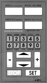
The Keys
Key | Basic functions |
A D | |
E F | |
1 2 ... 9 0 | |
G |
START of the Running-Machine / Running Belt
Alteration of speed
PAUSE Function
Alteration of elevation
Automatic modes / special functions (Manual, Profile, Cardio, Test)
Input of parameters (speed, time, pulse, a.s.)
Stop
Discontinuance of operation
The keys may also have special functions within different modes. See the instructions Manual mode, Profile Mode, Cardio Mode and Test Mode.
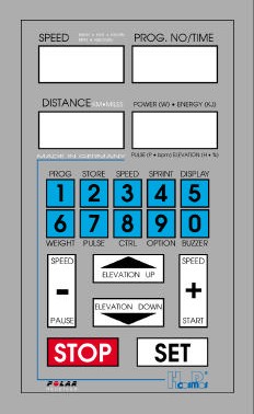
The Display
The display consists of 4 four digit LCD-displays, which show speed, running period, (energy consumption or wattage), running distance, elevation and Heart- Rate.
The indicated values remain, after stopping the Running-Machine, until:
K the Running-Machine has been started again with the D –key
K the display has been initiated by pressing the G –key once more.
If the Running-Machine has been stopped by reducing the speed with the A - key („PAUSE“-position), then the display continues with the previous values after starting again.
Marking | Display | Display / Unit | Resolution | Unit / Display under Option .. |
Speed | 0.1 km/h | m/s or mph | ||
Distance | a) 1 meter f) 1h / 1km. | miles e) (V) "2.25" f) Operating time & kilometers | ||
Prog. No. / Time | a) "P 10" | c) in "PULSE" mode, and automatic Speed Control Mode only | ||
Energy / Pulse Elevation | Calories e) Months / Year |
Speed
Pause
km/h
"PSE"
Distance
Oil interval
Service interval
Error code
EPROM version
Parameters
km
"OIL"
"HELP"
"E 20 ELE"
Program number
Time
Parameter input
min : sec
> "CTRL" PI.
Energy consumption
Power
Heart rate
Elevation
EPROM version
Parameters
KiloJoule
Watts
Beats/min
Percent %
> Option
> Option
1 KJ
1 Watt
1 beat/min
Version
1h / 1 km
Watts
1-9 sec
The "Energy - Pulse - Elevation" display shows the following values:
Operating Status | Display |
without change of elevation / without pulse | Energy consumption or Watts (depending on the setup of Options) |
without change of elevation / with pulse | Pulse |
with change of elevation | Elevation |
Mode of Operation:
The Running-Machine is equipped with several modes of operation: Manual, Profile, Cardio and Test. Some of the modes of operation can also be changed online into another while the Running-Machine is in operation.
The incorporated series interface RS 232 is always active. This means, that you can send and receive data/commands at any time (parallel) and during any mode. Always the latest command will be executed. No matter if the command came via RS 232 interface or from the UserTerminal during one of the 4 modes.
7 different acceleration levels and deceleration levels are available for all modes and for remote control via RS 232.
Max. Acceleration Level and minimum Acceleration Level see chapter: User Options / Optional Functions.
Acceleration Level | total Time from 0 to max. Speed |
1 | 131 seconds |
2 | 66 seconds |
3 | 33 seconds |
4 | 16 seconds |
5 | 8 seconds |
6 | 5 seconds |
7 | 3 seconds |
Manual Mode / Basic Functions MCU 2 & MCU 3
.D Start Running-Machine
Start the Running-Machine by pressing the "+" key. If this key is pressed several times, the speed of the Running-Machine will be increased step by step with higher acceleration level. The belt can be accelerated in up to 7 levels until the maximum speed is reached. See also setup of OPTION 40!
.C Maintain Speed
If the Ckey is pressed, the current speed will be kept constant. Depending on the setup of OPTION 40, the SET key may not be in use (may not be required to maintain the current speed). In this case the Speed will be maintained automatically after termination of pressing "+" or "-".
.A D Change Speed
Press the keys "+" and "-" in order to change the speed. If these keys are pressed several times, the belt can be accelerated or decelerated in different levels. Seven acceleration levels between maximum and minimum speed are available.
Acceleration Table
Acceleration Level | Acceleration / deceleration from 0 to maximum speed |
1 | 131 seconds |
2 | 66 seconds |
3 | 33 seconds |
4 | 16 seconds |
5 | 8 seconds |
6 | 5 seconds |
7 | 3 seconds |
The same times are valid for the deceleration of the Running-Machine. Under "OPTION 10" (see special function OPTION) the acceleration levels can either be blocked or released. For safety reasons a standard 5-second-delay of the motor control (inverter drive) is programmed; thus the acceleration levels 6 and 7 are somewhat delayed. This delay function can only optionally be released by H-P-COSMOS.
.E F Change Elevation
Use the E and F key in order to change the elevation.
.C Maintain Elevation
If the Ckey is pressed, the current elevation will be kept constant. Depending on the setup of OPTION 40, the SET key may not be in use (may not be required to maintain the current elevation).
.A Pause
Press the "-" key in order to stop the Running-Machine and activate the condition "PAUSE". "PSE" appears in the Speed display. The values of the distance covered, the time needed for this distance and the energy consumed will be "frozen".
If the run is to be aborted after this pause, press the "STOP" key. Press the "+" key in order to continue running after having the
pause ended. The recording is started from the current value so that despite an interruption the total running time, total distance and the total energy consumption can be read at the end of the measurement.
If a specific program step in an automatic program is to be paused, enter a speed of "0.1 km/h".
.G STOP - End Running
Press "STOP" and the run is ended. The elevation automatically returns to "0 %" (only various models, see OPTIONS). Press "STOP" again and the elevation reset is also stopped.
The values are displayed until a new run is started and they are automatically set to "0". Each program activity can prematurely be ended by pressing "STOP".
When using the Running-Machine with an elevation of more than 15 %, you should pay attention that the motor-driven brake is no longer working when the driving motor is switched off and that the test subject's weight is sufficient to drive the belt again. After having the STOP key pressed and if a specific elevation is set (limit depending on factory setting) the motor-driven brake can still be active. This, however, means that the driving motor works and current is consumed until the elevation is below the set limit again and the brake switches off automatically.
Should you have any further questions, please contact an authorised engineer.
Important: For a better documentation we recommend to use a printer linked to the serial interface RS 232 or/and to use an external PC with the Software H-P-COSMOS ParaGraphics®.
Automatic Mode / Special Functions
If a special function is called up, a specific number is to be entered (blinking insertion mark). Exception: "DISPLAY" and "BUZZER" function.
.1 Call up (start) a Program/Profile
Program type: | Memory location no.: | Remark: |
Fixed programs: | 01 to 20 | cannot be changed in the memory |
Test programs: | 21 to 29 | cannot be changed in the memory |
User programs: (freely programmable) | 30 to 89 | maximal 20 program steps per memory location |
User programs: (freely programmable) | 90 to 99 | maximal 80 program steps per memory location |
If the special function "PROG" is called up, enter a program number in the upper right display (blinking insertion mark). Single-digit or two-digit numbers can be entered. Two-digit numbers are to be entered within 3 seconds as otherwise the computer assumes that a single-digit number is to be entered.
The program will be started automatically after the countdown (three beeps) is expired or the "START" key is pressed before. A program can also be called up during a run without having to stop the device. If the program is started in such a way the displays will automatically be reset to "0".
If "PAUSE" is selected (indicated by "PSE" in the Speed display, also see manual operation, "PAUSE") during a program run, the program can be continued by pressing the "START" key. Based on the latest measured values, the recording will then be continued. Even during a program run another program can be started without having to stop the belt.
At any time a running program can be intervened by operating the program manually, using the speed preselection (function key "SPEED") or pressing "PAUSE" so that speed or elevation in an individual program step can be changed ON-LINE. Then, the original program list will again exactly be followed and the next program step of the program list will be activated.
The program step which has been changed ON-LINE will not be changed in the memory. The programs no. 01 to no. 29 cannot be changed or deleted in the memory.
The programs no. 30 to no. 99 are freely programmable by using the "STORE" function and can also be changed or deleted in the memory.
Program Overview for MCU 2 and MCU 3
Fixed Programs models without elevation
PROGR. NO.: | TIME | DISTANCE | MAX. SPEED | MAX. ELEVATION | ENERGY (65kg) |
1 | 5 min | 0.543 km | 8 km/h | 0 % | 154 KJ |
2 | 6 min | 0.677 km | 8 km/h | 0 % | 190 KJ |
3 | 8 min | 1.052 km | 12 km/h | 0 % | 291 KJ |
4 | 10 min | 1.455 km | 13 km/h | 0 % | 400 KJ |
5 | 18 min | 3.710 km | 17 km/h | 0 % | 980 KJ |
6 | 26 min | 4.649 km | 16 km/h | 0 % | 1252 KJ |
7 | 30 min | 5.843 km | 15 km/h | 0 % | 1569 KJ |
8 | 30 min | 5.250 km | 12 km/h | 0 % | 1419 KJ |
9 | 36 min | 7.293 km | 18 km/h | 0 % | 1949 KJ |
10 | 30 min | 4.697 km | 12 km/h | 0 % | 1283 KJ |
PROGR. NO.: | DISTANCE | TIME | MAX. SPEED | MAX. ELEVATION | ENERGY (65kg) |
11 | 0.5 km | 4:02 min | 12 km/h | 0 % | 140 KJ |
12 | 0.8 km | 7:34 min | 8 km/h | 0 % | 232 KJ |
13 | 1.0 km | 9:42 min | 9 km/h | 0 % | 291 KJ |
14 | 1.0 km | 9:10 min | 8 km/h | 0 % | 290 KJ |
15 | 1.2 km | 7:38 min | 13 km/h | 0 % | 338 KJ |
16 | 2.2 km | 11:43 min | 15 km/h | 0 % | 609 KJ |
17 | 3.2 km | 17:46 min | 14 km/h | 5 % | 863 KJ |
18 | 3.6 km | 20:09 min | 18 km/h | 0 % | 1001 KJ |
19 | 1.4 km | 13:53 min | 9 km/h | 0 % | 410 KJ |
20 | 2.0 km | 13:32 min | 14 km/h | 0 % | 510 KJ |
Fixed Programs models with elevation
PROGR. NO.: | TIME | DISTANCE | MAX. SPEED | MAX. ELEVATION | ENERGY (65kg) |
1 | 5 min | 0.543 km | 8 km/h | 0 % | 154 KJ |
2 | 6 min | 0.677 km | 8 km/h | 4 % | 199 KJ |
3 | 8 min | 1.052 km | 12 km/h | 0 % | 291 KJ |
4 | 10 min | 1.455 km | 13 km/h | 10 % | 441 KJ |
5 | 18 min | 3.710 km | 17 km/h | 20 % | 1178 KJ |
6 | 26 min | 4.649 km | 16 km/h | 18 % | 1486 KJ |
7 | 30 min | 5.843 km | 15 km/h | 10 % | 1765 KJ |
8 | 30 min | 5.250 km | 12 km/h | 0 % | 1419 KJ |
9 | 36 min | 7.293 km | 18 km/h | 4 % | 2019 KJ |
10 | 30 min | 4.697 km | 12 km/h | 25 % | 1573 KJ |
PROGR. NO.: | DISTANCE | TIME | MAX. SPEED | MAX. ELEVATION | ENERGY (65kg) |
11 | 0.5 km | 4:02 min | 12 km/h | 0 % | 140 KJ |
12 | 0.8 km | 7:34 min | 8 km/h | 5 % | 243 KJ |
13 | 1.0 km | 9:42 min | 9 km/h | 8 % | 317 KJ |
14 | 1.0 km | 9:10 min | 8 km/h | 15 % | 319 KJ |
15 | 1.2 km | 7:38 min | 13 km/h | 18 % | 356 KJ |
16 | 2.2 km | 11:43 min | 15 km/h | 10 % | 632 KJ |
17 | 3.2 km | 17:46 min | 14 km/h | 15 % | 907 KJ |
18 | 3.6 km | 20:09 min | 18 km/h | 8 % | 1122 KJ |
19 | 1.4 km | 13:53 min | 9 km/h | 24 % | 548 KJ |
20 | 2.0 km | 13:32 min | 14 km/h | 25 % | 905 KJ |
Test Programs models with elevation
Some test profiles (e.g. CONCONI-test, STEP-test, COOPER-test, etc.) are endurance tests (max. load and max.
Heart Rate tests) and should only be performed after consultation of a medical doctor and under supervision of trained staff.
Proper warm-up and cool-down periods have to be considered.
Use a safety harness with a safe chest belt system (optional equipment) for the subject when making max.
Load and max. Heart Rate Tests!
Test-mode can perform several different (predefined and selfdefined) tests. Information about the tests can be found in the enclosure. All Test Profiles only make the load control. There is no automatic evaluation done by the Running-Machine. The

evaluation has to be done by host equipment (e.g. ECG, Ergospirometry, etc.) or external PC Software (e.g. 789 Analysis Software)
Test No | Definition of Test / Profile | Comment / Programming | |
21 | CONCONI – TEST – Protocol | Endurance Test (max. Heart Rate Test) (e.g. for determination of anaerobic threshold via Heart Rate curve of the subject) Standard load profile: Starting Speed: 8 km/h, must be changed according the conditions of the subject Circuit (Lap length): 200m increment: 0.5 km/h STOP must be activated manually by the medical doctor when the subject is fully exhausted. | |
22 | CONCONI – TEST – Protocol | Endurance Test (max. Heart Rate Test) (e.g. for determination of anaerobic threshold via Heart Rate curve of the subject) Standard load profile: | |
23 | STEP – TEST – Protocol (Graded – Test - Protocol) | Endurance Test (max. Load Test) (e.g. for determination of anaerobic threshold by means of taking blood samples during the load-brakes and lactate analysis with external lactate analysing equipment. The Heart Rate should also be recorded! Standard load profile: | |
24 | COOPER – Protocol | Endurance Test (max. Heart Rate Test) elevation stays constant and the speed is going to be increased by 0.32 km/h every minute. | |
25 | BRUCE – Protocol | e.g. for ECG Stress-Test Step Duration Speed | Elevation 10.0 % 12.0 % 14.0 % 16.0 % 18.0 % 20.0 % 22.0 % |
26 | BALKE – Protocol | e.g. for ECG Stress-Test Step Duration Speed | Elevation 2.5 % 5.0 % 7.5 % 10.0 % 12.5 % 15.0 % 17.5 % 20.0 % 22.5 % 25.0 % |
27 | NAUGHTON – Protocol | e.g. for ECG Stress-Test Step Duration Speed | Elevation 0.0 % 3.5 % 7.0 % 10.5 % |
Starting Speed: 8 km/h, must be changed according the conditions of the subject
Circuit (Lap length): 200m (can be changed)
increment: 0.5 km/h (can be changed)
STOP must be activated manually by the medical doctor when the subject is fully exhausted.
Starting Speed: 8 km/h, must be changed according the conditions of the subject
Circuit (Lap Time): 3 min. (can be changed)
Brake Time: 30 sec. (can be changed)
Increment: 2.0 km/h (can be changed)
STOP must be activated manually by the medical doctor when the subject is fully exhausted.
Start at 5.3 km/h and 0% elevation.
after 1 minutes: elevation increase to 2 %
after 2 minutes: The elevation will be increased by 1% every minute.
when elevation is 25%:
STOP must be activated manually by the medical doctor when the subject is fully exhausted.
3 min 2.7 km/h
3 min 4.0 km/h
3 min 5.4 km/h
3 min 6.7 km/h
3 min 8.0 km/h
3 min 8.8 km/h
3 min 9.6 km/h
2 min 5.0 km/h
2 min 5.0 km/h
2 min 5.0 km/h
2 min 5.0 km/h
2 min 5.0 km/h
2 min 5.0 km/h
2 min 5.0 km/h
2 min 5.0 km/h
2 min 5.0 km/h
2 min 5.0 km/h
3 min 3.0 km/h
3 min 3.0 km/h
3 min 3.0 km/h
3 min 3.0 km/h
14.0 % 17.5 % | |||
28 | ELLESTAD A – Protocol | e.g. for ECG Stress-Test Step Duration Speed | Elevation 10.0 % 10.0 % 10.0 % 10.0 % |
29 | ELLESTAD B – Protocol | e.g. for ECG Stress-Test Step Duration Speed | Elevation 10.0 % 10.0 % 10.0 % 10.0 % 15.0 % 15.0 % |
3 min 3.0 km/h
3 min 3.0 km/h
3 min 2.7 km/h
3 min 4.8 km/h
3 min 6.4 km/h
3 min 8.0 km/h
3 min 2.7 km/h
3 min 4.8 km/h
3 min 6.4 km/h
3 min 8.0 km/h
3 min 8.0 km/h
3 min 9.6 km/h
User Profiles
30 - 89 | free definable user profile / not scaleable | max. 20 Program steps each Program |
90 - 99 | free definable user profile / not scaleable | max. 99 Program steps each Program |
Further profiles can be created via an external PC and software ParaGraphics®.
Important: For a better documentation we recommend to use a printer linked to the serial interface RS 232 or/and to use an external PC with the Software H-P-COSMOS ParaGraphics®.
.2 Enter Program / User-Profiles
This function can only be activated if the belt is stopped.
Program Memory Locations
No. 30 - 89 freely programmable in 20 program steps each No. 90 - 99 freely programmable in 80 program steps each
Parameter Input per Program Step
0.2 - 45 km/h | Resolution 0.1 km/h | |
7 levels | with OPTION | |
1 sec. up to 99 min. | ||
10 m up to 99 km | ||
0 - 25 % | Resolution 1.0 % |
Speed:
Acceleration levels:
Time:
Distance:
Elevation:
Select Memory Location
After having the special function "STORE" selected, a program number for the freely programmable memory locations no. 30 to no. 99 is to be entered (blinking insertion mark in the upper right display).
After having the program number entered and if this memory location is still free and not programmed, enter the speed for the first program step in the Speed display.
The program step, for example "S 01", will be shown in the Distance display.
3 seconds after having the program number entered, a beep indicates that this memory location is already programmed. The program number will disappear again.
A memory location which is already programmed will be secured by a write protection. In this case select another free memory location.
If an already programmed memory location is to be changed or deleted, follow the procedure described under point "Program Correction, Modifications".
Programming
The parameters for each individual program step are to be entered in the following order:
Acceleration Level > if desired, only, "OPTION" function; Standard Level 1 (see programming examples)
Speed (3-digit e. g. "080" for 8,0 km/h or "100" for 10,0 km/h)
Time or distance (switch over with "0000")
Elevation
The "+" and "-" keys as well as the "UP" and "DOWN" keys serve as cursor keys during the programming procedure. Press the "+" and "-" keys in order to change between the individual displays and use the "UP" and "DOWN" keys in order to select the individual program steps.
The above-mentioned keys also allow to correct entry errors or to scroll through the program. The programmed parameters always refer to the current program step and not to the "current" time or distance indicated in the program.
If all of the parameters are entered, confirm the last program step "STOP" by pressing the "SET" key.
Thus, the program is automatically saved, too. Program step no. 1 appears again in order to check the program once again by scrolling through, to make necessary corrections or to end the programming procedure by pressing the "STOP" key.
Even if the Running-Machine is switched off, the entered program will still be saved in the memory.
Acceleration Level
In addition to the manual setting the stepwise acceleration and deceleration of the Running-Machine can be programmed for each individual program step. Up to 7 levels between maximum and minimum speed can be selected.
After having the program number entered, the speed for the first program step is to be entered (blinking insertion mark in the Speed display).
Before entering the speed, press the "OPTION" function key. Another blinking insertion mark appears at the left side. Now enter the desired acceleration level and then the speed (3-digit number).
If a higher acceleration level is not desired, the speed can be entered immediately. Then, level "1" will be selected automatically. Acceleration table:
Acceleration level number | Acceleration from 0 to maximum speed |
1 | 131 seconds |
2 | 66 seconds |
3 | 33 seconds |
4 | 16 seconds |
5 | 8 seconds |
6 | 5 seconds |
7 | 3 seconds |
The same times are valid for decelerating the Running-Machine. Under "OPTION 10" (see special function OPTION) the acceleration levels can either be blocked or released.
Speed
The speed is always to be entered as a 3-digit number. Example:
0 0 8 | for | 0.8 km/h |
0 5 4 | for | 5.4 km/h |
1 6 0 | for | 16.0 km/h |
Duration - Time
The duration is always to be entered in minutes and seconds (4-digit number). Example:
0 0 2 0 for 20 seconds
0 5 0 0 for 5 minutes
8 0 0 0 for 80 minutes
If the time "0 0 0 0" is entered, the next entry field appears in the display. Enter the distance for this program step. The current program step will then be shown in the Time display. If instead of the distance a specific time is to be programmed again, enter "0 0 0 0" for the distance.
Distance > Length
First the speed is to be entered; following that enter the duration.
If "0 0 0 0" is entered for the time, the display switches over to the distance entry field for this program step. The current program step will then appear in the Time display.
If "0 0 0 0" is entered for the distance, the display again switches over to the duration which is to be entered for this program step. The distance is always entered in meters x 10.
Example:
0 0 0 5 for 50 meters
0 0 2 5 for 250 meters
0 2 0 0 for 2.0 kilometers
0 0 0 for 20 kilometers
Pause
A pause as a program step in an automatic program can be programmed by entering a speed of "0.1 km/h". Following that the duration of the pause can be programmed.
As the belt is not running during the pause, it is impossible to program a distance.
During the run the speed will be reduced until the Running-Machine stops (0 km/h) and "PSE" (Pause status) appears in the Speed display. The time will continue to run until the next program step becomes active.
End of Program, Saving
After having entered all of the parameters confirm the last program step "End of program > 0 km/h" by pressing the "SET" key. Thus, the program will also be saved.
Once again Program step no. 1 appears in order to scroll through the program, to make possible corrections or to end programming by pressing the "STOP" key.
A correction has to be saved by pressing the "SET" key.
Even if the Running-Machine is switched off, the entered program will be saved.
Program Correction, Program Modifications
The program storage can only be corrected in the user programs 30 to 99.
A memory location which is already programmed is protected by a write protection.
seconds after pressing the special function "STORE" and entering a program number, a beep can be heard and the program number will disappear again.
If this procedure is repeated for three times, program step 1 of the memory location which is already programmed will be active again.
The "+" and "-" keys as well as the "UP" and "DOWN" keys serve as cursor keys during the programming procedure. Press the "+" and "-" keys in order to change between the individual displays and use the "UP" and "DOWN" keys in order to select the individual program steps. Use the above-mentioned keys to scroll through the program.
Select and modify the corresponding program step.
After having performed all modifications they have to be saved once again by pressing the "SET" key. Then this function can be ended by pressing the "STOP" key.
Delete Program
A program memory location can be deleted in the user programs 30 to 99, only.
A memory location which is already programmed is protected by a write protection.
3 seconds after having the special function "STORE" and a program number entered, a beep can be heard and the program number will disappear again.
If this procedure is repeated for three times, program step 1 of the memory location which is already programmed will be active again.
Enter a speed of "00.0" in the first program step and save this entry by pressing the "SET" key and the program will be deleted.
Programming Examples for MCU 2 and MCU 3
Running phase | Program step | Time / Distance | Speed | Elevation |
Warm up phase | 1 | 4:00 min | 5.0 km/h | 0 % |
Increase of speed | 2 | 2:00 min | 8.0 km/h | 0 % |
Light uphill running | 3 | 2:00 min | 8.0 km/h | 5 % |
Sprint with high speed | 4 | 200 meters | 16.0 km/h | 0 % |
Cool down phase | 5 | 4:00 min | 6.0 km/h | 0 % |
STOP | 6 | 0.0 km/h | 0 % |
Programming on memory location no. 33:
Procedure | Prog. step | Input | Description |
1) | STORE 33 | Enter the program number for a memory location which is to be programmed. If this memory location is free, the tens digit for entering the speed will blink and program step "S 01" will appear in the Distance display. If the memory location is already used, the command "STORE 33" is to be entered four times (overwriting protection) in order to edit or delete this memory location. A used memory location can be deleted by entering a speed of "00.0" in the first program step and saving this entry by pressing the "SET" key. | |
2) | 1 | 050 | Enter the speed 5.0 km/h |
3) | 1 | 0400 | Enter the time 4:00 min. |
4) | 1 | 00 | Enter an elevation of 00 % |
"S 02" for program step no. 2 automatically appears in the Distance display. | |||
5) | 2 | 080 | Enter the speed 8.0 km/h |
6) | 2 | 0200 | Enter the time 2:00 min |
7) | 2 | 00 | Enter an elevation of 00 % |
"S 03" for program step no. 3 automatically appears in the Distance display. | |||
8) | 3 | 080 | Enter the speed 8,0 km/ |
9) | 3 | 0200 | Enter the time 2:00 min |
10) | 3 | 05 | Enter an elevation of 5 % |
"S 04" for program step no. 4 automatically appears in the Distance display. | |||
11) | 4 | OPTION 4 | If the "OPTION" key is pressed, another digit position which indicates the acceleration and delay level will blink at the left side of the Speed display. If "4" is entered, acceleration level 4 is selected. Following that the target speed is to be entered. If no higher acceleration level is entered after having the "OPTION" key pressed, the slowest step "1" will be selected automatically. |
12) | 4 | 160 | Enter the sprint speed 16.0 km/h |
13) 14) | 4 4 | 0000 0020 | With this entry the program step "S 03" will be displayed in the Time display and the distance can be entered as a parameter in the Distance display. Enter a distance of 200 meters [00.20 km] for the sprint distance |
15) | 4 | 00 | Enter an elevation of 00 % |
"S 05" for program step no. 5 automatically appears in the Time display. | |||
16) | 5 | OPTION 3 | Enter delay step 3 [free selection between 1 and 7] for the following target speed. If no higher delay step is entered after having "OPTION" pressed, the slowest step "1" will be selected automatically. |
17) | 5 | 060 | Enter the speed 6.0 km/h |
18) | 5 | 0000 | With this entry the program step "S 04" will be displayed in the Distance display again and the time can be entered as a parameter in the Time display. |
19) | 5 | 0400 | Enter the time 4:00 min |
20) | 5 | 00 | Enter an elevation 0 % |
"S 06" for program step no. 6 automatically appears in the Distance display. |
21) | 6 | SET | End the program and automatic saving |
Once again, "S 01" for program step no. 1 automatically appears in the Distance display. Use the "+" and "-" keys or the "UP" and "DOWN" keys in order to scroll through the individual entry fields and program steps. If one or the other setting is to be corrected, this correction is to be saved once again by pressing the "SET" key. | |||
22) | STOP | End programming procedure. | |
The program number under which the program has been saved will shortly appear in the Time or Prog. No. display. | |||
23) | PROG 33 | Call up of program which has just been saved. |
If a speed of "0" is entered in order to program a "Pause", select a speed of "00.1".
.3 Preselection of Speed
With this function the target speed can be selected before or during the run. 3 seconds after pressing this key, the Running- Machine will automatically start with the programmed speed.
If the "START" key is pressed after entering the target speed, the countdown will be avoided so that the belt can immediately be started with programmed target speed.
In order to achieve a higher acceleration level, press the "+" key several times during the acceleration.
Press the "-" key in order to decelerate the belt.
Pressing the "OPTION" key following the "SPEED" key, another digit position blinks in the Speed display which shows the acceleration or deceleration level.
Enter a number between 2 and 7 in order to select an acceleration level which will then be activated automatically. After that the target speed has to be entered.
If no higher acceleration level is selected after pressing "OPTION", the slowest step "1" will be used automatically.
.4 Sprint Programming: Acceleration up to max. Speed

!
For safety reasons this function is always blocked in "OPTION 13, Parameter 0".
The Running-Machine always speeds up to max. speed of the Running-Machine until you press STOP.
Only trained subjects are allowed to use this function in the presence of expert staff.
After pressing this key, you are asked to enter a specific time in seconds. This time corresponds to the acceleration time (time required to reach the maximum speed when the belt was stopped before).
This function will be started automatically after a countdown of 3 seconds.
If the time is entered, the belt can be started immediately by pressing the "START" key so that the countdown is avoided.
The Running-Machine always speeds up to max. speed of the Running-Machine until you press STOP.
.5 Selection of Display / Display Scrolling
Press this key and you can change between the displays of "Pulse" (if available), "Elevation" (if available) and energy consumption.
Without changing the displays or some seconds after changing the displays, the most important values will appear here:
Operating status | Display |
without changing the elevation without pulse | Energy consumption / Watts (see selection in Options) |
without changing the elevation with pulse | Pulse (Heart Rate) |
with changing the elevation | Elevation |
.6 Entry of the Subject's Body Weight
Press this key and the weight (kg) can be entered. The figure 65 for a standard weight of 65 kg is blinking in the "Energy - Pulse - Elevation" display.
Now enter the test subject's weight (2- or 3-digit value):
Example:
70 | for | 70 | kg |
105 | for | 105 | kg |
If the body weight is not entered for calculating (estimating) the energy consumption / Wattage, an average weight of 65 kg will be assumed and, based on this weight, the energy consumption (KJ) & Watts (W) will be calculated (estimated) and displayed.
.7 Heart-Rate-Dependent Exercise Control (Cardio Mode)

he pulse measurement, this function is not included in the standard equipment and is available as an option, only.
Pay attention to the notes on safety indicated in the instruction manual.
If the test subject complains about nausea or dizziness, the training is to be terminated immediately and a physician is to be consulted.
If the radio transmission of heart rate is disturbed (or such a disturbance is suspected) the automatic exercise control must not be used.
The system must not be used without prior instruction by expert staff.
Like t
Fields of Application
The pulse-dependent exercise control is intended for an automatic control of the Running-Machine with the aim to reach the pre-set heart rate of the test subject.
Three parameters can be programmed:
the desired heart rate (pulse) during the training
the maximum running speed
the maximum elevation
Depending on the selected parameters the following control sequences are possible:
Max. speed | Max. elevation | Control |
0 | 0 | No control |
> 0 | 0 | Speed control |
0 | > 0 | Elevation control |
> 0 | > 0 | Speed control first. After having reached the speed which is maximally allowed, the elevation will be controlled. |
Default Values
For safety reasons maximum values for heart rate and exercise parameters are to be entered.
These default values can be programmed and activated via the option functions after selecting the device switched on and the PULSE function.
Even if the Running-Machine is switched off, the default values will remain saved.
Thus, an easier operation is possible as default values are always pre-set when activating the PULSE function by pressing the "START" key.
Default values can be entered for:
Heart rate: Option 17 > Preselection: HR 120
Max. speed: Option 18 > Preselection: 8 km/h
Max. elevation Option 19 > Preselection: 25 %
Control
Based on the decision matrix supposed and tested by the Sporthochschule Magglingen (Switzerland), the Running-Machine approaches the preselected training rate:
HR difference bpm act > < predefined | ### Speed km/h | ### Elevation % | ### Time s |
> 50 | 2.0 | 2.7 | 20 |
> 30 | 1.0 | 1.3 | 15 |
> 15 | 0.5 | 0.7 | 10 |
> 5 | 0.2 | 0.3 | 10 |
> 3 | 0.1 | 0.1 | 10 |
Example:
If the current heart rate is 100 bpm and the programmed training heart rate is 160 bpm, the difference between both values is greater than 50 (see line 1). Thus, every 20 seconds the speed will be increased by 2.0 km/h. If the adjustment is based on the elevation, the elevation will be increased by 2.7 % every 20 seconds.
As soon as the heart rate of 156 bpm (difference of 4 bpm > see line 5) is reached, only every 10 seconds the speed or elevation will be readjusted by 0.1 km/h (or 0.1 %).
If the heart rate is in one of the first four ranges, "P" is blinking and the current heart rate appears in the display. As soon as the target rate (entered training rate +/- 3 bpm) is reached, "P" will blink, only.
Activation of Pulse-Dependent Exercise Control
New Start:
Press the "PULSE" key when the Running-Machine is stopped.
Use the control panel in order to enter a training rate or accept the default value by pressing the "START" key at once. (If you do not select a new training rate, the current value will be shown in the display for about 20 seconds.)
After selecting the training rate, press the "START" key.
On-Line Start:
If the Running-Machine is running, activate the pulse-dependent exercise control by pressing the "PULSE" key (new training rate is to be entered or the latest entered training rate is to be accepted) or selecting the command "CTRL 1" (if the latest entered training rate is accepted).
Change of Training Heart Rate and Parameters
The training rate and the adjustment parameters maximum speed and maximum elevation can be modified at any time without having to change the default values.
Command "PULSE" Training heart rate > (default value option 17) Command "CTRL 2" Max. speed > (default value option 18) Command "CTRL 3" Max. elevation > (default value option 19)
After entering the training rate these values will be shown in the corresponding displays for about 3 seconds.
The adjustment will be made as already described:
Three parameters can be programmed:
desired heart rate (pulse) during the training
maximum running speed
maximum elevation
Depending on the selected parameters the following adjustment sequences are possible:
Max. speed | Max. elevation | Adjustment |
0 | 0 | no adjustment |
> 0 | 0 | adjustment of speed |
0 | > 0 | adjustment of elevation |
> 0 | > 0 | At first adjustment of speed. After having reached the allowed maximum speed, the elevation is adjusted. |
Example:
Actual value of current heart rate: 100 bpm (beats per minute) Programmed training heart rate: 160 bpm
Allowed maximum speed: 10 km/h
Allowed max. elevation: 25 %
Response of pulse-dependent adjustment:
Every 20 seconds the speed will be increased by 2.0 km/h.
At first the speed is step-by-step adjusted up to a maximum of 10 km/h, unless a heart rate of 160 bpm is reached before. A beep of 2 seconds indicates that the allowed maximum speed of 10 km/h is required and achieved.
Following that the elevation will be further increased at a constant speed (in this case 10 km/h) until the desired heart rate of 160 (+ / - 3) bpm is achieved.
If necessary, the elevation will be reduced step by step until a value of 0 % is reached should the heart rate be higher than 163 bpm. If the heart rate (+ / - 3 bpm) is out of the target rate, "P" and the current heart rate will blink in the display. If the target rate (entered training rate) is reached, only "P" will blink and the heart rate will be displayed constantly.
Deactivate the Pulse-Dependent Adjustment
Press the "STOP", "-" key or
press the "CTRL 0" key without stopping the Running-Machine or
enter the training rate "000" (key "PULSE" 0).
After deactivating the pulse-dependent adjustment, the values for training rate, max. speed and max. elevation will always be reset to the default values, except when the "-" key is pressed.
.8 Control Function / Activation
This function is intended for parameter entry and ON-LINE deactivation and activation of the pulse-dependent adjustment and Automatic Speed Control Function.
Pulse-Dependent Exercise Control
"CTRL 0" Deactivation of pulse-dependent adjustment without having to stop the Running-Machine. "CTRL 1" Reactivation of the exercise control during running (also possible via function key "PULSE"). "CTRL 2" ON-LINE correction of max. speed > (default value option 18)
"CTRL 3" ON-LINE correction of max. elevation > (default value option 19)
Automatic Speed-Control-Function / Position Sensor
Detailed instruction see chapter: Optional Equipment: Automatic Speed-Control-Function / Position Sensor
"CTRL 4" Activation of Automatic Speed-Control-Function / Position Sensor (see instruction under optional equipment) (position dependent Speed-Control-Function)
As an optional equipment a position sensor (measurement via a thread [yarn] system) is available. This sensor measures:
the actual position of the subject on the running track
the deviation of the target position to the actual position of the subject
According to the deviation of the target position to the actual position of the subject, the speed of the Running- Machine will be controlled automatically.
Start this function with CTRL 4 and the actual position of the subject will be considered automatically as the
Target-Position.
"CTRL 5" Deactivation of Automatic Speed-Control-Function
.9 Option Key / Functions
After entering an option number, one of the option functions will be activated.
The option functions are intended for default settings, service and calling up of parameters. Depending on the option corresponding parameters will be displayed or specific settings can be made. Examples:
"OPTION 01" The OIL message is deleted.
"OPTION 05" The EPROM firmware version is displayed in the lower displays. "OPTION 10 3" 3 acceleration levels have been released in option no. 10.
OP no. | Para meters | Description / Function | Default settings | from EPROM version |
01 | Delete error messages (OIL, HELP and ERROR). The required maintenance work has to be performed before deleting error messages! The H-P-COSMOS service department has to be contacted before one of the service displays or error codes will be deleted! | 01 | ||
02 | Indication of: total DISTANCE covered | 01 | ||
03 | Indication of: total TIME operated (belt operated incl. stand-by mode) | 01 | ||
04 | Indication of: total TIME operated (only belt operated) | 01 | ||
05 | Indication of: EPROM firmware version | |||
10 | 1 to 7 | Acceleration / Delay level limitation Select this function and a number will blink in the "PULSE, ELEVATION, ENERGY" display. This number indicates the maximum acceleration level (step). In the step test / graded test (Prog. 23) the set maximum level will be used automatically. | 4 | 01 |
11 | 0 | Countdown between the program steps deactivated. The countdown (3 short beeps) before starting a program is always activated. | 1 | 01 |
11 | 1 | Countdown (3 short beeps) before the next program step in an automatic program is started. | 1 | 01 |
12 | 0 | Speed display in km/h Running-Machine: Speed: km/h Distance: km | 0 | 01 |
12 | 1 | Speed display in mph Running-Machine: Speed: mph (miles per hour) Distance: miles | 0 | 01 |
12 | 2 | Speed display in m/sec Running-Machine: Speed: m/s (meter per second) Distance display: km | 0 | 01 |
13 | 0 | "SPRINT" (function key no. 4) sprint function blocked (until about May 1995 "ACCEL") For safety reasons this function has to be blocked! See function key "SPRINT" | 0 | 01 |
13 | 1 | "SPRINT" (function key no. 4) sprint function released (until about May 1995 "ACCEL") For safety reasons this function has to be blocked! See function key "SPRINT" | 0 | 01 |
14 | 0 | Heart rate – display interval "beat to beat" | 0 | |
14 | 1 to 9 | Heart rate – display interval 1 to 9 seconds. Compare: The original POLAR watch has a display interval of 5 seconds. | 0 | |
15 | CODE | Heart rate measurement – unlock display By entering a secret 4-digit code you can unlock the display for heart rate measurement | ||
15 | CODE | Heart rate measurement – lock display By entering a secret 4-digit code you can lock the display for heart rate measurement | ||
16 | 0 | Normal rotating direction of running belt Different types of Running-Machine. Depending on type this function is activated via a manual key-operated switch and not via keystroke under option 16. This procedure must only be performed when the belt is stopped. From 1994 this function has been replaced by a key switch. | 0 | 2.13 |
16 | 1 | Reverse direction of running belt rotation. | 0 | 2.13 |

H-P-COSMOS Sports & Medical Treadmill - Ergometer
_!: Service@!:
file: Manual H-P-COSMOS Treadmill MCU2 EPROM 2.31 + MCU3.doc
created: 06.02.2001
printed: 12.10.2001
page: 32 of 71
Different types of Running-Machines. Depending on type, this function is activated via a manual key-operated switch and not via keystroke under option 16. This procedure must only be performed when the belt is stopped. From 1994 this function has been replaced by a key switch. | ||||
17 | 0 - 250 | Default value heart rate for "PULSE" (Cardio Mode) function If the „PULSE“ function key is pressed, the default value will automatically be displayed. This value can then be accepted immediately by pressing the START key. The value which is mostly required for the pulse-dependent adjustment will be set as default value. | 120 | 2.15 |
18 | 0 - 45 | Default value max. speed for "PULSE" (Cardio Mode) function. If the „PULSE“ function key is pressed, the default value of the heart rate will automatically be displayed. This value can then immediately be accepted by pressing the START key. Following that the value of the allowed maximum speed during the pulse-dependent adjustment will blink in the display for 3 seconds. The most frequently used value will be set as a default value. | 8 | 2.15 |
19 | 0 - 25 | Default value max. elevation for "PULSE" (Cardio Mode) function. If the „PULSE“ function key is pressed, the default value of the heart rate will automatically be displayed. This value can then immediately be accepted by pressing the START key. Following that the value of the allowed maximum elevation during the pulse-dependent adjustment will blink in the display for 3 seconds. The most frequently used value will be set as a default value. | 25 | 2.15 |
20 | 0 | RS 232 interface protocol "CosRec" Running-Machine can only send data but no data can be received by them. The "CosRec" protocol is, for example, intended to transfer data to the PC software "ParaGraphics" (DOS) of H-P-COSMOS. Connection cable available on request. | 2 | |
20 | 1 | RS 232 interface protocol "SCHILLER ECG" Running-Machine can send and receive data. Running-Machine can be controlled via the SCHILLER ECG type AT 60 or CS 100. Connection cable on request. | 2 | |
20 | 2 | RS 232 interface protocol "CosCom" Running-Machine can send and receive data. The "CosCom" protocol is, for example, intended to transfer data to the PC software ParaGraphics® (Windows) of H-P-COSMOS. Connection cable available on request. | 2 | |
20 | 3 | RS 232 interface protocol "PRINTER" All data of Speed, Time, Elevation, Distance and Heart Rate will be sent to a printer. Use serial printer type or parallel printer type with converter. Connection cable and converter available on request. Interface Parameter: Baudrate: 9600, Data bits: 8, Parity: no, Stop bits: 1 The transmission interval can be adjusted in OPTION 52 | 2 | 2.25 |
20 | 4 | RS 232 interface protocol JAEGER "OXYCON" OXYCON software from 3.12a (from Nov. 1994) on. Running-Machine can send and receive data. The Running-Machine can be controlled via a JAEGER/Mijnhardt ergospirometry system OXYCON. Connection cable available on request. Information on the exact data format for the interface on request. From 01.01.2000 all JAEGER ergospirometry systems & running machines are equipped with H-P-COSMOS series interface RS 232 CosCom© protocol (OPTION 20 2). So please us the CosCom© protocol for these machines. | 2 | 2.17 |
20 | 5 | RS 232 interface protocol "Marquette MAX1" ECG This protocol is optional, please ask H-P-COSMOS Running-Machine can send and receive data. The Running-Machine can be controlled via a Marquette MAX 1 ECG measuring station. Connection cable available on request. Information on the exact data format for the interface on request. | 2 | Up to Version 2.25: Standard / Version 2.30 or higher: Option |
20 | 6 | RS 232 Trackmaster emulation in km/h. Example: Marquette HELLIGE PC ECG CardioSys.This protocol is optional, please ask H-P-COSMOS | 2 | |
20 | 7 | RS 232 Trackmaster emulation in mph. Example: Marquette HELLIGE PC ECG CardioSys.This protocol is optional, please ask H-P-COSMOS | 2 | |
20 | 8 | RS 232 custo card ECG Protocol This protocol is an OPTION, please ask H-P-COSMOS. From 01.01.2000 all CUSTO ECG equipment are equipped with H-P-COSMOS series interface RS 232 CosCom© protocol (OPTION 20 2) which is standard. So please us the CosCom© protocol for these machines. | 2 | |
20 | 9 | RS 232 Loop-back Interface-Test An external test-plug (available at H-P-COSMOS) for the RS 232 port is equipped with 1 LED and a switch. During the test mode (OPTION 20 9) please change position of the switch in order to check the blinking time (frequency) of the LED in both positions of the switch: | 2 |
Uphill running with elevation.

H-P-COSMOS Sports & Medical Treadmill - Ergometer
_!: Service@!:
file: Manual H-P-COSMOS Treadmill MCU2 EPROM 2.31 + MCU3.doc
created: 06.02.2001
printed: 12.10.2001
page: 33 of 71
Important: After the test do not forget to reset the protocol to the standard | ||||
22 | 0 | Analog interface deactivated (use the code "2071" for deactivation) Elevation and speed cannot be controlled with analog voltages of 0 - 5 V at the separate socket. | 0 | |
22 | 1 | Analog interface activated (use the code "1702" for activation) Elevation and speed can, for example, be controlled by an external ECG with analog voltages of 0 - 5 V at the separate socket. If 0 - 10 Volt are used a voltage divider has to be integrated in the connection cable or the Running-Machine or ladder ergometer. Running-Machine can only receive analog signals; they cannot send analog signals. A special analog interface box for a complete analog communication is available on request. Attention! If this inquiry is activated by mistake and the device is not controlled via analog voltage, the Running-Machine can be controlled via their own control panel at the MCU, speed and elevation, however, will remain almost "0" as the analog values and thus the "predicted values" are "0", too. | 0 | |
23 | 0 - 45 | Max. SPEED with analog control If the Running-Machine is controlled via the analog interface and operated with 5 V, the maximum speed of the Running-Machine can be programmed. If 0 - 10 Volt are used a voltage divider has to be integrated in the connection cable or the Running-Machine or ladder ergometer. | 0 (km/h) | |
24 | 0 - 30 | Max. ELEVATION with analog control If the Running-Machine is controlled via the analog interface and operated with 5 V, the max. elevation can be programmed. If 0 - 10 Volt are used a voltage divider has to be integrated in the connection cable or the Running-Machine or ladder ergometer. | 0 (%) | |
26 | 0 to 20 | Tolerance-Range (non SPEED CONTROL range) of "automatic Speed-Control-Function / Position Sensor" See chapter: optional equipment. The value in Option 26 represents 1/256 x 2 (x 2 is for +/- range) of the total thread length of the position sensor. | 10 | 2.23 |
27 | 1 ... 6 | Acceleration / Deceleration (Delay) Level of "automatic Speed-Control-Function / Position Sensor" See chapter: optional equipment Pay attention to possible Acceleration-Limitations under Option 10, OP18 & OP29 | 2 | 2.23 |
28 | 1 .... 5 | minimum Acceleration / Delay Level (all modes) With OPTION 28 1 ... 5 you can set the minimum executed Acceleration Level. That means: If you press the key D or A 1 time only, the acceleration level according to following table will be executed. Time from 0 to max. speed: Acceleration Level total Time 1 131 s 2 66 s 3 33 s 4 16 s Example for setup: OPTION 28 3 This means, that for every speed command (manual mode, program mode, remote control via RS 232 interface) the acceleration level 3 will be active. So it takes 33 seconds from 0 to max. speed. (max. Acceleration Level see OPTION 10) | 1 | 2.23 |
29 | 1 | minimum Acceleration / Delay Level (RS 232 interface mode only) With OPTION 29 1. 7 you can set the minimum executed Acceleration Level for incoming speed commands via RS 232. That means: If you receive a speed command from any host equipment (PC, ECG, ergospirometry, etc.), the acceleration level according to following table will be executed. Time from 0 to max. speed: Acceleration Level total Time 1 131 s 2 66 s | 1 | 2.23 |
LED blinking in one switch position "short time", in the other switch position "long time": Interface is OK
LED blinking in both switch positions "short time": Input defective
LED blinking only in one switch position "long time": Change wires of Input and Output of the Sub-D-Port
LED not blinking: Output defective
8 s
5 s
3 s

H-P-COSMOS Sports & Medical Treadmill - Ergometer
_!: Service@!:
file: Manual H-P-COSMOS Treadmill MCU2 EPROM 2.31 + MCU3.doc
created: 06.02.2001
printed: 12.10.2001
page: 34 of 71
3 33 s 4 16 s Example for setup: OPTION 29 3 This means, that for every speed command during remote control via RS 232 interface the acceleration level 3 will be active. So it takes 33 seconds from 0 to max. speed. This option was designed especially for graded test or cardiopulmonary stress tests, when the Running-Machine is controlled from an external ECG or ergospirometry equipment and the Running-Machine needs to speed up or slow down very fast. (max. Acceleration Level see OPTION 10) | ||||
Option 30 to Option 99 are locked and only accessible for authorised service engineers via a secret access code. Do not change following factory set-ups without prior communication with H-P-COSMOS. | ||||
30 | 0 - 9 | Backwards movement of elevation motor (Only for models QUASAR®, QUASAR®-med and PULSAR®) If you change elevation to "ELEVATION UP" the elevation motor (only the gear-box types) is recommended to move slightly (1 to 2 mm) towards reverse direction (elevation down) after finishing "ELEVATION UP". This action helps to have a "mechanical tolerance" of the gear-box and the chain- system with the pulleys. After restart of "ELEVATION UP" the elevation motor will have much less mechanical load for the first 1 or 2 mm, and so the motor can start much smoother. The time (distance) for the backwards movement can be adjusted. OPTION 30 0: no backwards movement OPTION 30 2: short backwards movement (= factory setting) OPTION 30 9: long backwards movement For models MERCURY and Ergo-Track II the factory setting is „0“ | 2 | |
31 | Length of Running-Belt (Only required for manual speed calibration. In case you program the device type code [see OPTION 49] instead of manual speed calibration, this optional function is not required) MERCURY, STELLAR, QUASAR, PULSAR and Ergo-Track: 3000 - 4000 mm Default value: 3400 mm Running-Machine SATURN 250-75: 5000 - 7000 mm Default value: 5600 mm Running-Machine: VENUS©: Default value: 4540 mm Ladder Ergometer: DISCOVERY: 5000 - 6000 mm Default value: 5335 mm Continue with instructions OPTION 32 | 3400 | ||
32 | 1 | manual SPEED Calibration: activated for measuring increments (Only required for manual speed calibration. In case you program the device type code [see OPTION 49] instead of manual speed calibration, this optional function is not required) After activation of OPTION 32 1 the number of increments (measured by the speed sensor) will be displayed in the DISTANCE and HEART RATE display (see them as 1 display with 8 digits during this function!). | 0 | |
8 s
5 s
3 s
Measure the length of the running belt in mm with the help of a measuring tape. The belt must be tightened correctly.
Allowed values for various Running-Machine types are: Running-Machine
Make a reference mark with a color pen or chalk on the running belt.
Make a reference mark with a color pen or chalk on the sliding platform or on the sidewalk. Preferable at "half length".
Make sure that the 2 reference marks match.
Activate OPTION 32 1
Make exactly 3 revolutions with the running belt.
Move the running belt by hand at mainly slow but constant speed.
Caution! The running belt must only be moved in the normal direction. Never change the direction not even for some millimeters; the speed/distance sensor will count every mm of this movement and you'll have false calibration!
Make sure that the reference marks match exactly after the 3rd revolution.
Write down the value (increments counted) indicated in the DISTANCE and HEART RATE displays to the H-P-COSMOS service report: OP 32

H-P-COSMOS Sports & Medical Treadmill - Ergometer
_!: Service@!:
file: Manual H-P-COSMOS Treadmill MCU2 EPROM 2.31 + MCU3.doc
created: 06.02.2001
printed: 12.10.2001
page: 35 of 71
See also OPTION 30 and 34 | ||||
32 | 0 | manual SPEED Calibration: save measured increments (Only required for manual speed calibration. In case you program the device type code [see OPTION 49] instead of manual speed calibration, this optional function is not required) See also OPTION 30 and OPTION 32 1 and OPTION 34 | 0 | |
33 | 0 | Elevation system sensor type: hole-bar hole-bar (hole-rod) for elevation systems 0 – 30% (resolution 1.0 %) models QUASAR® and PULSAR® built from 1988 to February 1992 | ||
33 | 1 | Elevation system sensor type: incremental disk 60 increments diameter of incremental disk: 80 mm for elevation systems 0 – 25% (resolution 0.1 %) models QUASAR®, PULSAR®, VENUS©, SATURN®, LE 300C, LE 500C, LE 580C, LE 600C built from March 1992 | ||
33 | 2 | Elevation system sensor type: incremental disk 100 increments diameter of incremental disk: 100 mm for elevation systems 0 – 25% (resolution 0.1 %) models QUASAR®, PULSAR®, VENUS©, SATURN® built from March 1992 until May 1992. | ||
33 | 3 | Elevation system sensor type: analog voltage measurement Running-Machine Model SATURN: thread (yarn) system: Analog voltage 0 %: 0.3125 Volts Analog voltage 25 %: 3.7500 Volts Running-Machine Model MERCURY & LE 200C (built 1994 to 1997), Ergo-Track II: Potentiometer system: Analog voltage 0 %: 0.0 Volts Analog voltage 20 %: 5.0 Volts | 2.17 | |
34 | manual Speed calibration: indication of value (counted increments from the speed sensor per 10 m belt distance) (Only required for manual speed calibration. In case you program the device type code [see OPTION 49] instead of manual speed calibration, this optional function is not required) See also OPTION 30 and OPTION 32 1 and OPTION 34 This is only the automatic calculated value for increments per 10 meters of running belt distance. Write down the value (increments calculated) indicated in the DISTANCE and HEART RATE displays to the H-P-COSMOS service report: OP 34 Allowed (tolerated) values for all different models from 3,000 to 11,000 increments. Details see list below: Running-Machine STELLAR, QUASAR, PULSAR, LE 250C - LE 500C, Ergo-Track III and IV: Speed sensor incremental disk 36 holes: ca. 3,440 increments (built from 1988 to 1992) Speed sensor incremental disk 60 slots: ca. 5,740 increments (built from 1992) Speed sensor incremental disk 100 slots: ca. 9,565 increments (built only 1992) Running-Machines MERCURY, LE 100C - LE 200C (built 1994 to 1997) Ergo-Track I and II (built 1994 to 1997): Speed sensor incremental disk 60 slots: ca. 4,660 increments Running-Machines SATURN, VENUS, LE 580C, LE 600C: (all values are allowed / tolerated) Speed sensor incremental device with 2500 increments / motor revolution ca. 110,580 increments Speed sensor incremental disk 60 slots: ca. 3560 increments | |||
35 | 500 to 5000 km | "OIL interval due" indication The distance interval for indication of "OIL" service required can be adjusted by means of OPTION 35. Standard interval is 1,000 km. OIL intervals then will be indicated with error code "E01" Do not change the interval without prior communication with H-P-COSMOS. Some of the models VENUS©, SATURN®, ORBITER©, LE 580, LE 600, LE 700 OPTION 35 is not adjustable, in case the machines are equipped with an automatic OIL-Pump and a tank. | 1000 km | |
36 | ELEVATION 0% "DIGITAL-Value" for analog elevation sensor (all models listed below built from 1994 to 1997) Model MERCURY, LE 200C, Ergo-Track II: Potentiometer sensor system | "15" MERCURY & LE 200C |
Save the value by entering: OPTION 32 0
Repeat 3 times steps 4 to 10 of this instruction and write down all of the 3 values. In case the result of the 3 independent measurements is almost the same (tolerance 5 %) you have finished the manual speed calibration. In case the result of the 3 independent measurements differs a lot (tolerance more than 5 %) please check the speed/distance sensor.

H-P-COSMOS Sports & Medical Treadmill - Ergometer
_!: Service@!:
file: Manual H-P-COSMOS Treadmill MCU2 EPROM 2.31 + MCU3.doc
created: 06.02.2001
printed: 12.10.2001
page: 36 of 71
Model SATURN: thread (yarn) sensor system Instruction: In case the now measured (or entered) digital value exceeds the value "50", the value will be resetted to the default value (10 for SATURN® and 15 for MERCURY©). Only in case of unexpected problems enter a digital value with the help of the numeric keyboard. Contact H-P-COSMOS in this case. Explanation for the indicated "digital value": The voltage range (see OPTION 33 3) will be divided by 256 values. The actual measured voltage value will be converted to a digital value and the be indicated in the MCU display. | Ergo-Track "10" SATURN | |||
37 | ELEVATION 15% (MERCURY© / LE 200C) "DIGITAL-Value" for analog elevation sensor ELEVATION 25% (SATURN®) "DIGITAL-Value" for analog elevation sensor (all models listed below built from 1994 to 1997) Model MERCURY, LE 200C, Ergo-Track II: Potentiometer sensor system Model SATURN: thread (yarn) sensor system Instruction: Adjust an elevation of 15 % (25 % model SATURN®) Use a measuring tape at the front of the Running-Machine frame to ensure you are really at the adjusted elevation. SATURN®) will be indicated in the display. In case the now measured (or entered) digital value is less than the value "150" (< "200" model SATURN®), the value will be resetted to the default value "150" ("200" for SATURN®). Only in case of unexpected problems enter a digital value with the help of the numeric keyboard. Contact H-P-COSMOS in this case. 6. Write down the value (increments calculated) indicated in the displays to the H-P-COSMOS service report. Explanation for the indicated "digital value": The voltage range (see OPTION 33 3) will be divided by 256 values. The actual measured voltage value will be converted to a digital value and the be indicated in the MCU display. | "198" MERCURY & LE 200C Ergo-Track | ||
"246" SATURN | ||||
38 | 1,000 to 9,999 km | "SERVICE interval due" indication The distance interval for indication of regular SERVICE required (interior cleansing, checking drive belts, etc.) can be adjusted by means of OPTION 38. Standard interval is 5,000 km. SERVICE intervals then will be indicated with error code "E02" Do not change the interval without prior communication with H-P-COSMOS. | 5,000 | 2.18 |
39 | 0 to 99 % | Elevation value, until the motor control can not be switched off When using elevation (uphill and/or downhill) the motor works as a drive system and as a brake system at the same time. But if you stop the running belt at higher elevation (from 8% to 35 %) the motor will be switched off and can not work as a brake system any more. So the belt may be accelerated due to the body weight of the subject and the gravity. To prevent from this unwanted acceleration this OPTION can be activated with a number of models (not with all models!). Example: | 0 | 2.18 |
Before you start OPTION 36: Adjust an elevation of 0 %. Use a measuring tape at the front and at the back of the Running-Machine frame to ensure you are really at 0 %.
In case 0 % can not be achieved (maybe the elevation system will be switched off before 0% by the MCU) start "OPTION 36" and enter the value "0". Start "ELEVATION DOWN" again and adjust 0% elevation.
Start OPTION 36. The digital value for 0 % elevation will be indicated in the display.
The value will be saved automatically if you do not enter a digital value by hand, or if you press the STOP key.
Write down the value (increments calculated) indicated in the displays to the H-P-COSMOS service report.
Before you start OPTION 37:
In case elevation 15 % (25 % model SATURN®) can not be achieved (maybe the elevation system will be switched off before by the MCU) start "OPTION 37" and enter the value "255" for MERCURY©, LE 200C or Ergo-Track II ("255" for SATURN®). Start "ELEVATION UP" again and adjust 15% elevation (25 % model SATURN®).
Start OPTION 37. The digital value for 15 % elevation (25 % model
The value will be saved automatically if you do not enter a digital value by hand, or if you press the STOP key.
to prevent from unwanted running belt surge / running belt acceleration
only models with elevation and only active for models built 1988 to 1998. Explanation:

H-P-COSMOS Sports & Medical Treadmill - Ergometer
_!: Service@!:
file: Manual H-P-COSMOS Treadmill MCU2 EPROM 2.31 + MCU3.doc
created: 06.02.2001
printed: 12.10.2001
page: 37 of 71
OPTION 39 10: If the elevation is 10% or more, then the motor will not be switched off when pressing the STOP key. The belt (motor) will continue to move at very low speed, maybe 0.1 or 0.2 km/h. (Only if you press the red emergency OFF button, the power supply will be cut and the machine fully stops). Caution! Beware of unwanted belt acceleration when pressing STOP or Emergency Off. | ||||
40 | 0 | Acceleration & Elevation Function: automatic ("SET") For changing SPEED and Elevation you need to press the keys „+“ or "-" or "UP or "DOWN" for a short time only. Speed and Elevation will increase or decrease to maximum value until you confirm (maintain) the present value with the key "SET". This setup ("automatic acceleration") is not recommended for customers with many different users (in fitness clubs, hotels, etc.) because the users need to understand how to confirm (maintain) present speed/elevation. | 1 | 2.25 |
40 | 1 | Acceleration & Elevation Function: manual acceleration (no "SET" function) For changing SPEED and Elevation you need to press the keys „+“ or "-" or "UP or "DOWN" as long as you want to change the values. The key "SET" is not required to confirm (maintain) the present value. This setup ("automatic acceleration") is recommended for customers with many different users (in fitness clubs, hotels, etc.) because the users can easy understand how to change and maintain speed/elevation. | 1 | 2.25 |
41 | Display test of the MCU UserTerminal Displays After activation of this Option: A line of 4 dashes will appear on all 4 displays: 1st one is blinking. After pressing any key: All display segments (digit "8") and the "." (dot) will appear. After pressing another key: End of display test. | |||
42 | 0 - 9 | Direct Speed control by analog voltage from MCU to the inverter drive. This function is only for diagnosis and for error search for speed / power related problems. Enter analog voltage from 1 9 volts (resolution 1 volt). Caution / Danger! The running belt will accelerate extremely fast without any delay!! In the SPEED display the increments per 1/100 second, received from the speed sensor, will be indicated. This function is for diagnosis. Under this condition there is no speed compensation caused by alterating loads, or caused by malfunction of inverter drive or caused by speed sensor problems. Example 1: If the real speed is constant but the display is alterating, the problem may be the speed sensor. Example 2: If the real speed and also the display is alterating, the problem may be the inverter or the power supply. | 0 | |
43 | 5 - 50 | max. Speed limitation Caution! Release max. Speed limitation temporarily in case you need to check the real max. speed for the self diagnosis system according to Option 48 | 25 | |
44 | MCU 2 0 to 9999 km or miles
MCU 3 0 to 9999 meter or miles/1000 | Distance Interval for activating automatic OIL-PUMP (only for Running-Machines VENUS©R & SATURN® R, LE 600 R) After covering the programmed distance (in km or miles: see setup in OPTION 12) the OIL-PUMP for lubrication of running surface will be activated for a while (programmable in OPTION 45). Please contact H-P-COSMOS before changing any setup!! The belt and deck may be damaged in case the setup is wrong! | ||
45 | MCU 2 0 – 99 min.
MCU 3 0 to 99 (0.6 sec. to 60 sec. | Time Interval for activating automatic OIL-PUMP (only for Running-Machines VENUS©R & SATURN® R) Time period, how long the OIL-PUMP is activated according to the distance intervals programmed in Option 44. Please contact H-P-COSMOS before changing any setup!! The belt and deck may be damaged in case the setup is wrong! | ||
46 | 0 - 25 / 0 - 30 | max. Elevation limitation The max. Elevation of the Running-Machine can be limited. 0 % 30 % Example: This function is useful if the height of the room's ceiling is not enough when using an arch construction with safety harness. | 25 / 30 | 2.25 |
47 | 0 | Reset of Oil (Lubrication)-Interval-Display A reset of the oil interval display prior to automatic indication can be required only after a regular lubrication. | 0 |

H-P-COSMOS Sports & Medical Treadmill - Ergometer
_!: Service@!:
file: Manual H-P-COSMOS Treadmill MCU2 EPROM 2.31 + MCU3.doc
created: 06.02.2001
printed: 12.10.2001
page: 38 of 71
47 | 1 | Reset of Service-Interval-Display A reset of the service interval display prior to automatic indication can be required only after a regular service. | 1 | |
48 | 5 - 50 | Speed Value at max. Speed. (for Speed-Measurement Self Diagnosis: "E30" error message) It is of great importance to check the real max. speed of the Running-Machine during 10 volts analog control signal from the MCU to the inverter. Caution! Before you can check the max. speed of the Running-Machine you must ensure (and release if required) that in "Option 43" there is no software limitation for the max. speed. Explanation: The MCU observes and compares the measured and received speed signal from the speed sensor to the speed command sent from the MCU. If the 2 values do not match within a certain tolerance, the error message "E30" will be indicated on the MCU UserTerminal. This is for detection of dusty or false adjusted speed sensors, weak power supply to the drive motor or for other speed related problems. | 2.25 | |
49 | 010 | Selection of Device Type (with MCU 2 / MCU 3) For an easier device dependent setup of the values for the speed calibration (Option 31, 32) and the elevation sensor system (Option 33). Options 31, 32 and 33 are still functioning if necessary, but setup via this Option 49 and entering the device code (for example "010 = QUASAR®) is preferred. Devices (Standard version): 010 QUASAR, Ergo-Track IV 0-22 km/h 012 QUASAR 0-44 km/h 050 PULSAR, LE 500C 0-44 km/h Speed-Calibration-Value: 5872 Elevation System: Yes Elevation System: 60 incr. Disc 020 STELLAR, Ergo-Track III 0-22 km/h 022 STELLAR 0-44 km/h Speed-Calibration-Value: 5872 Elevation System: No 011 QUASAR 0-36 km/h Speed-Calibration-Value: 3874 Elevation System: Yes Elevation Sensor System: 60 incr. Disc 021 STELLAR 0-36 km/h Speed-Calibration-Value: 3874 Elevation System: No 500 MERCURY, LE 200C 0-22 km/h (built 1994-1997) 501 MERCURY 0-10 km/h (built 1994-1997) Speed-Calibration-Value: 4666 Elevation System: Yes Elevation Sensor System: Analog (with Potentiometer) 502 STRATOS, Ergo-Track I 0-18 km/h (built 1994-1997) Speed-Calibration-Value: 4666 Elevation System: No Devices (SATURN): Speed-Calibration-Value: 2610 Elevation System: Yes Elevation Sensor System: 60 incr. Disc Devices (VENUS): Speed-Calibration-Value: 2610 Elevation System: Yes Elevation Sensor System: 60 incr. Disc Device (Ladder-Ergometer DISCOVERY©): 400 DISCOVERY Ladder-Ergometer Speed-Calibration-Value: 1243 | 2.23 |
QUASAR-med, LE 300C 0-22 km/h
QUASAR-med 0-15 km/h
STELLAR-med 0-22 km/h
STELLAR-med 0-15 km/h
SATURN
VENUS
Elevation System: No | ||||
50 | 0 | Control Characteristic of "automatic Speed Control Function / Position Sensor" See chapter: optional equipment If the subject leaves the Tolerance-Range: The speed will be controlled (accelerated or decelerated) until the subject gets back to the TARGET-Position. | 1 | 2.24 |
50 | 1 | Control Characteristic of "automatic Speed Control Function / Position Sensor" See chapter: optional equipment If the subject leaves the Tolerance-Range: The speed will be controlled (accelerated or decelerated) until the subject gets back to the Tolerance-Range. | 1 | 2.24 |
50 | 2 | Control Characteristic of "automatic Speed Control Function / Position Sensor" See chapter: optional equipment If the subject leaves the Tolerance-Range: The speed will be controlled (accelerated or decelerated) until the ACTUAL-Position of the subject does not move further away from the TARGET-Position. | 1 | 2.24 |
51 | 0 | KiloJoule Display: Energy / Load Energy consumption of the subject in KiloJoule. | 0 | 2.24 |
51 | 1 | WATT Display: Energy / Load Load (Watts) to the subject during running | 0 | 2.24 |
51 | 2 | WATT Display: Energy / Load Load (Watts) to the subject during walking | 0 | 2.24 |
52 | 0 – 99 | Printout Interval (in sec.) of series interface RS 232 / printer interface | 10 | |
80 | 0 | Only for Running-Machines VENUS, SATURN from 1997: Controlling Frequency Inverter analog or digital Controlling of Frequency Inverter analog 0-10V/ 4-20mA | 0 | 2.25 |
80 | 1 | Only for Running-Machines VENUS, SATURN from 1997: Controlling Frequency Inverter analog or digital Controlling of Frequency Inverter KEB digital via RS232/RS485 Works only with Frequency Inverter from KEB! | ||
81 | Only for Running-Machines VENUS, SATURN from 1997: Emergency Stop 1 stop time and parameter setup The value consists of three digits. First digit select the parameter setup (0 = slow stop or 1 = fast stop), the second and third digit select the stop time in 0,1sec. Example: Value 135 means: On actuating Emergency Stop 1 the parameter setup will be switched to 1 (fast stop) and the analog voltage will go down from 10Volts to 0Volts in 3,5 seconds. | |||
82 | Only for Running-Machines VENUS, SATURN from 1997: Emergency Stop 2 stop time and parameter setup The value consists of three digits. First digit select the parameter setup (0 = slow stop or 1 = fast stop), the second and third digit select the stop time in 0,1sec. Example: Value 135 means: On actuating Emergency Stop 2 the parameter setup will be switched to 1 (fast stop) and the analog voltage will go down from 10Volts to 0Volts in 3,5 seconds. | |||
83 | Only for Running-Machines VENUS, SATURN from 1997: Emergency Stop 3 stop time and parameter setup The value consists of three digits. First digit select the parameter setup (0 = slow stop or 1 = fast stop), the second and third digit select the stop time in 0,1sec. Example: Value 135 means: On actuating Emergency Stop 3 the parameter setup will be switched to 1 (fast stop) and the analog voltage will go down from 10Volts to 0Volts in 3,5 seconds. | |||
84 | Only for Running-Machines VENUS, SATURN from 1997: Emergency Stop 4 stop time and parameter setup The value consists of three digits. First digit select the parameter setup (0 = slow stop or 1 = fast stop), the second and third digit select the stop time in 0,1sec. Example: Value 135 means: On actuating Emergency Stop 4 the parameter setup will be switched to 1 (fast stop) and the analog voltage will go down from 10Volts to 0Volts in 3,5 seconds. | |||
85 | Only for Running-Machines VENUS, SATURN from 1997: Emergency Stop 5 stop time and parameter setup The value consists of three digits. First digit select the parameter setup (0 = slow stop or 1 = fast stop), the second and third digit select the stop time in 0,1sec. Example: Value 135 means: On actuating Emergency Stop 5 the parameter setup will be switched to 1 (fast stop) and the analog voltage will go down from 10Volts to 0Volts in 3,5 seconds. | |||
86 | 10.0 | Only for Running-Machines VENUS, SATURN from 1997: Setting the Speed for analog output 1Volt = x km/h In this option the speed is set for 1 Volt analog output. Example: Value 4 means: 1 Volt analog output the Treadmill is running with 4 km/h. | ||
87 | 10.0 | Only for Running-Machines VENUS, SATURN from 1997: |
Setting the Elevation for analog output 1Volt = x % In this option the elevation is set for 1 Volt analog output. Example: Value 4 means: 1 Volt analog output the Treadmill has an elevation of 4%. | ||||
88 | 0 | Only for Running-Machines VENUS, SATURN from 1997: Speed-Measurement Here the Speed-Measurement is set. Parameter 0: Speed-Measurement with increment disc 60 increments, the Speed- Calibration-Value (Option 34) is 2610 | ||
88 | 1 | Only for Running-Machines VENUS, SATURN from 1997: Speed-Measurement Here the Speed-Measurement is set. Parameter 1: Speed-Measurement with increment measure-system 2500 increments, the Speed-Calibration-Value (Option 34) is 1091 | ||
99 | Secret Code to release Options 30 98 „Factory Setting“: locked The code is only available at H-P-COSMOS for authorized service engineers! By entering a secret 4-digit-code you can release the Options 30 98 which are only designed for authorized service engineers / factory settings. The code does not appear in the display. From EPROM version 2.18 (MCU 2) Options 30 98 will be locked automatically after disconnection from the mains (power off). | |||
99 | Secret Code to lock Options 30 98 „Factory Setting“: locked The code is only available at H-P-COSMOS for authorized service engineers! By entering a secret 4-digit-code you can lock the Options 30 98 which are only designed for authorized service engineers / factory settings. The code does not appear in the display. From EPROM version 2.18 (MCU 2) Options 30 98 will be locked automatically after disconnection from the mains (power off). During the 1st operation hour (total operation time of the MCU) the automatic lock of the Options 30 98 does not work; they must be locked manually. Consider this when incorporating a new MCU as a spare part. |
.0 Pulse Buzzer
The pulse buzzer beeps in the rhythm of the heart beat can be switched on and off with this key. This function is for acoustic observation if the heart rate is symmetrical.
It can be used also for detection of interference of the heart rate signal by peripheral equipment and devices.
Optional Equipment and Features
Handrails adjustable in height and width
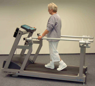
Illustration 1: Side View: Handrails adjustable in height and width Order no. COS10030 (for MERCURY & STRATOS family)
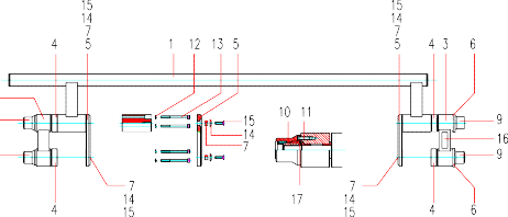
Illustration 2: Handrails adjustable in height and width: details of single components
Rehab-Attachment / ArmSupport for partial body weight support & safety
Depending on the model a Rehab-Attachment or ArmSupport is available for body weight support of a subject:
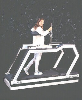
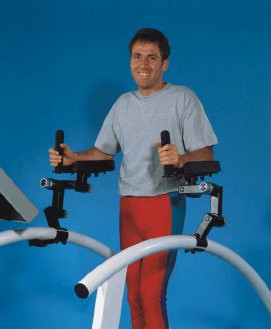
Illustration 3: Rehab-Attachment Illustration 4: ArmSupport (for MERCURY© family)
Order no. 000 9611 0010 Rehab-Attachment Order no. 000 9806 0044 ArmSupport
Partial Body Weight Support / AirWalk Unweighting System with Vest
For partial body weight support and unweighting (for example for "Locomotion Therapy") a pneumatic unweighting system is available including "suspension garment” (Vest).
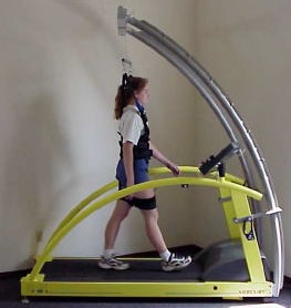
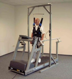
Illustration 5: AirWalk 35 arch version Illustration 6: AirWalk 35 Stand-alone version Order no. COS10117 Order no. COS10091
Safety Arch with Harness and Chest-Belt-System
This optional system is highly recommended for maximum load tests (CONCONI, Graded-Tests, etc.).
When the subject is falling (pull the harness with weight load more than 8 kg) an automatic STOP switch stops the running belt.
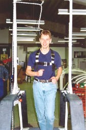
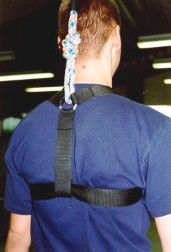
Illustration 7: Safety Arch with Harness and Chest-Belt-System
Order no. 000 9701 0014 (for STELLAR & QUASAR family with 63 cm running track width) Order no. 000 9701 0016 (for VENUS & SATURN family with 75 cm running track width) Order no. 000 9701 0026 (for VENUS & SATURN family with 100 cm running track width)
If the height of the room's ceiling is not enough when using an arch construction with safety harness, the max. Elevation of the Running-Machine can be limited: See OPTION 46
Running Belt Rotation reversible for Downhill Run

!
As the subject is running against the usual running belt rotation and therefore has no control of the UserTerminal it is
necessary to have a supervisor who controls the Running-Machine during the training.
For safety reasons the max. speed has been limited with the models possessing a cross-bar handrail or a motor case cover.
Use a safety harness for additional safety!
The function running belt rotation reverse (optional) permits a simulation of a downhill run. To prevent any abuse, the function can only be activated by a key-operated switch.
Change from forward to reverse belt rotation
Turn the key switch and start the machine without a subject on the running belt. Operate at approx. 5 km/h speed.
Observe the belt position for 2 minutes and correct the belt position with the left belt adjustment screw (see chapter maintenance and belt adjustment). It is normal, that after changing the belt rotation, the belt will move to one side and therefore the running belt needs to be readjusted to the center of the running track.
Once the belt is readjusted, STOP the belt and operate the machine with the subject on the belt.
Attention:
If the key-operated switch is being activated at stand still, the running belt rotation reverse will be in function at the next start.
Change from reverse to forward belt rotation
Turn the key switch and start the machine without a subject on the running belt. Operate at approx. 5 km/h speed.
Observe the belt position for 2 minutes and correct the belt position with the left belt adjustment screw (see chapter maintenance and belt adjustment). It is normal, that after changing the belt rotation, the belt will move to one side and therefore the running belt needs to be readjusted.
Once the belt is readjusted, STOP the belt and operate the machine with the subject on the belt.
In most cases the readjustment of the running belt requires the same revolutions of the left belt adjustment screw.
Therefore we recommend to note the required revolutions of the belt adjustment screw. This will help to avoid the waiting time and can reduce the belt adjustment procedure to some seconds effort.
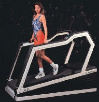
Illustration 8: Reverse of Belt Rotation (for walking downhill)
Order no. 000 9611 0009 (for STELLAR & QUASAR family)
Digital (Serial) Interface RS 232

Connecting a Running-Machine to a medical device results in a medical system. Only authorized trained staff is
entitled to perform this connection.
This medical system, when connecting a Running-Machine to a medical device. has to be connected via a potential- balance-cable with the provided connector bolt and with the provided bearing within the medically used room.
The interface serves as a data transmitter from the Running-Machine to a PC or other controlling devices. You can also control the Running-Machine from another controlling device (ECG, o.a.) or with the appropriate Software from a PC, via interface.
Standard for all devices is ONE serial interface COM 1.
For further information please contact your local dealer or H-P-COSMOS.
The RS 232 interface protocol CosCom© is available on request and can be found at www.coscom.org
The incorporated protocols (e.g. for ECG-devices) are listed in the list of options under OPTION 20
List of compatible host equipment (ECG, Ergospirometry, etc,)
Compatibility of all H-P-COSMOS Running-Machine models with ECG- and Ergospirometry Systems
System | Hersteller Manufacturer | Typ Type | RS 232 Protokoll Interface Protocol | Laufband Setup Treadmill Setup |
Ergospirometry | JAEGER / Germany | OXYCON | H-P-COSMOS CosCom© | see Option 20 or 21 |
Ergospirometry | Mijnhardt / Holland | OXYCON | H-P-COSMOS CosCom© | see Option 20 or 21 |
Ergospirometry | Cosmed / Italy | K 4 b² / Quark b² Quark PFT | H-P-COSMOS CosCom© | see Option 20 or 21 |
Ergospirometry | CORTEX / Germany | MetaMax | H-P-COSMOS CosCom© | see Option 20 or 21 |
Ergospirometry | SensorMedics / USA | via EKG | SCHILLER CS 100 | see Option 20 or 21 |
Ergospirometry | SensorMedics / USA | via EKG | HELLIGE/Trackmaster | see Option 20 or 21 |
Ergospirometry | ZAN / Germany | ZAN 600 | H-P-COSMOS CosCom© | see Option 20 or 21 |
PC – EKG | JAEGER / Germany | MasterScreen | H-P-COSMOS CosCom© | see Option 20 or 21 |
PC – EKG | custoMed / Germany | custo card | custo card | see Option 20 or 21 |
PC – EKG | custoMed / Germany | custo card m | H-P-COSMOS CosCom© | see Option 20 or 21 |
PC – EKG | CardioControl / NL | Cardio Perfect | H-P-COSMOS CosCom© | see Option 20 or 21 |
PC – EKG | Norav Medical | 1200B & 1200S | H-P-COSMOS CosCom© | see Option 20 or 21 |
PC – EKG | Cosmed / Italy | Cardiovis / PLUS | H-P-COSMOS CosCom© | see Option 20 or 21 |
PC – EKG | PBI Pulse Biomedical | QRS Card | H-P-COSMOS CosCom© | see Option 20 or 21 |
PC – EKG | Marquette/HELLIGE / GE | CardioSoft | Trackmaster in km/h | see Option 20 or 21 |
PC – EKG | Marquette/HELLIGE / GE | CardioSoft | Trackmaster in mph | see Option 20 or 21 |
PC – EKG | Marquette/HELLIGE / GE | CardioSys | Trackmaster in km/h | see Option 20 or 21 |
PC – EKG | Marquette/HELLIGE / GE | CardioSys | Trackmaster in mph | see Option 20 or 21 |
PC – EKG | OXFORD Instruments | Medilog QRS Card | H-P-COSMOS CosCom© | see Option 20 or 21 |
PC – EKG | Dr. Vetter / Germany | PC EKG plus / ultra | Trackmaster in km/h | see Option 20 or 21 |
EKG | Marquette/HELLIGE / GE | CardioSmart | Trackmaster in km/h | see Option 20 or 21 |
EKG | Marquette/HELLIGE / GE | CardioSmart | Trackmaster in mph | see Option 20 or 21 |
EKG | ergoline / Germany | EK 3012 | custo card | see Option 20 or 21 |
EKG | SCHILLER | AT 60 | SCHILLER (Pacer) | see Option 20 or 21 |
EKG | SCHILLER | CS 100 | SCHILLER (Pacer) | see Option 20 or 21 |
EKG | Marquette / USA | MAX 1 | Marquette | see Option 20 or 21 |
EKG | ESAOTE / Italy | Trackmaster in km/h | see Option 20 or 21 | |
Blood-Pressure | SunTech Medical | Tango | H-P-COSMOS CosCom© | see Option 20 or 21 |
PC Software | H-P-COSMOS | H-P-COSMOS ParaGraphics® DOS | H-P-COSMOS CosRec© | see Option 20 or 21 |
PC Software | H-P-COSMOS | H-P-COSMOS ParaGraphics® Win | H-P-COSMOS CosCom© | see Option 20 or 21 |
PC Software | H-P-COSMOS | H-P-COSMOS ParaGraphics® NT | H-P-COSMOS CosCom© | see Option 20 or 21 |
PC Software | H-P-COSMOS | H-P-COSMOS Virtual UserTerminal | H-P-COSMOS CosCom© | see Option 20 or 21 |
PC Software Treadmill-Trainer | HUR / Finland | Treadmill-Trainer | H-P-COSMOS CosCom© | see Option 20 or 21 |
Test-Plug for RS 232 Port | H-P-COSMOS | LED + switch | H-P-COSMOS Loop-Back | see Option 20 or 21 |
© 2001 H-P-COSMOS E & OE.
Furthermore there is a tiny hand held Running-Machine simulator available for adapting your PC, ECG or ergospirometry equipment to our Running-Machine. This device with keyboard and display, can simulate all functions of the Running-Machine ergometer and can be controlled via series interface RS 232.
Interface Cable RS 232 for the PC Personal Computer
To be used for H-P-COSMOS ParaGraphics®, H-P-COSMOS Virtual UserTerminal, PC ECGs, Ergospirometry Devices.
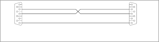
Laufband / treadmill CONNECTOR DB9
Stecker / male
PC COM1 oder COM2 CONNECTOR DB9
Buchse / female
6
7
8
9
1
2
3
4
5
R x D T x D
GND
1
2
3
4
5
6
7
8
9
For connecting your PC to the Running-Machine you need an interface cable (optional equipment) 9-pole Sub- D (male - female) with crossed transmission- receive- cable (PIN 2 and PIN 3).
Illustration 9: RS 232 interface cable for PC
Order no. 000 9701 0034 for 5 m length / Order no. 000 9701 0035 for 10 m length
Interface Cable RS 232 for connection to ECG Schiller
Connection cable between Running-Machine and ECG Schiller AT 10 / AT 60 or CS 100 / CS 200
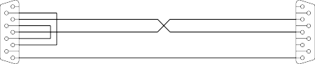
1
R x D
T x D
5
GND
1
2
3
4
5
4
3
2
6 6
7 7
8 8
9 9
EKG / ECG Schiller CONNECTOR DB9
Stecker / male
Laufband / treadmill CONNECTOR DB9
Stecker / male
Illustration 10: RS 232 interface cable for ECG Schiller Order no. 000 9701 0036 for 5 m length
Interface Cable RS 232 for connection to Ergospirometry JAEGER OXYCON
OXYCON Alpha / Delta / Champion / Pro: Connect the Running-Machine interface with an available serial interface (COM1 ... COM4) at the PC of the OXYCON. Do not use the female connector at the OXYCON with the letters "Treadmill / Running- Machine".
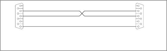
Laufband / treadmill CONNECTOR DB9
Stecker / male
OXYCON CONNECTOR DB9
Buchse / female
6
7
8
9
1
2
3
4
5
R x D T x D
GND
1
2
3
4
5
6
7
8
9
Important: From January 2000 use CosCom© RS 232 interface protocol!
Illustration 11: RS 232 interface cable for OXYCON Ergospirometry
Order no. 000 9701 0034 for 5 m length / Order no. 000 9701 0035 for 10 m length
Analog Interface / Interface Converter
An Interface Converter is available as an optional equipment.
Elevation and speed can be controlled by an external ECG or Ergospirometry with analogue voltages of 0 - 5 Volts (or 0 – 10 Volts) at the separate socket. Furthermore analogue output signal for Elevation and Speed of the Running-Machine as well as an analogue signal for the Heart Rate of the subject is available for host equipment. So with this interface converter a complete analogue communication is possible. For further details please contact H-P-COSMOS.
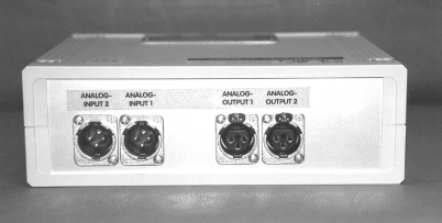
Illustration 12: H-P-COSMOS Interface Converter: AD / DA / DD Order no. 000 9611 0027 (for all H-P-COSMOS Running-Machines)
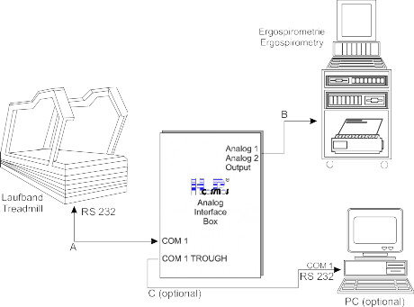
Illustration 13: Application Example for H-P-COSMOS Interface Converter: AD / DA / DD
Printer Protocol
Connect the printer (with a serial interface) via interface cable with the serial interface RS 232 of the Running-Machine. Attention: For a printer with a parallel interface you will need a commercial interface-converter, available in every computer- store or at H-P-COSMOS (order no. COS10056 interface converter).
If Option 20: 3 is chosen (printer protocol see list of options), following data will be printed out via a serial printer:
H-P-COSMOS Sports & Medical / Germany
http://www.H-P-COSMOS.com Sports&Medical@H-P-COSMOS.com Running Machine exercise/test protocol Date: 04.09.1998 22.35 (Datum)
Time (hh:mm:ss) Distance (km) Speed (km/h) Elevation (%) Heart Rate (bpm)
00:00:00 | 0.000 | 0.0 | 0.0 | 62 |
00:00:10 | 0.022 | 5.0 | 0.0 | 80 |
00:00:20 | 0.044 | 5.5 | 0.0 | 82 |
00:00:30 | 0.066 | 5.5 | 0.5 | 84 |
00:00:40 | 0.104 | 8.5 | 1.8 | 96 |
00:00:50 | 0.125 | 8.5 | 7.6 | 102 |
00:01:00 | 0.150 | 12.8 | 4.4 | 108 |
00:01:10 | 0.200 | 3.4 | 0.0 | 104 |
Heart Rate Measurement System 789
Please pay attention to the safety instructions in the instruction manual.
Stop training immediately if feeling sick or dizzy and see your doctor.
In the case of interference do not rely on the indicated values of the wireless Heart-Rate transmission.
!
Chest Belt and 789 Transmitter
You can use all 789 transmitters (coded and uncoded) with your H-P-COSMOS treadmill. For treadmills with EPROM versions lower than V 2.31 an EPROM update is available at H-P-COSMOS for the use of coded transmitters.
Note: Even with using the coded senders the transmission of the heart rate to the treadmill is still uncoded. The transmitter is only activated if placed correctly on the body.
The chest belt is washable. In this case loosen the belt from the transmitter. Please take care not to crush the two electrodes of the belt. After having loosened the transmitter off the belt, wash the belt and especially the electrodes with warm water and mild soap.
Do not clean the electrodes mechanically! Do not use alcohol!
Radius of Transmission
The transmitter radius amounts to approx. 80 to max. 120 cm. If you run several Running-Machines or other training devices on the same heart rate measurement system, you should keep a gap of at least 100 cm between the devices to exclude interference.
Battery of the 789 Transmitter
At an average application of 2 hours per day the life-span of the battery amounts to approx. 1 year.

!
The 789 receiver is incorporated in the Running-Machine and requires no battery. It is supplied by the Running-Machine. If an irregular pulse display occurs in spite of an unobjectionable technical condition, please check your pulse manually or in case of doubts see your doctor for a check.
Correct Placement of 789 Transmitter Belt
Adjust the belt length so that the belt fits tightly but does not confine you. The belt should not loosen while exercising. Close the belt with transmitter placed outwards (789-Logo in right position).
In order to allow an optimal skin contact the skin should be moist. Contact gel, as used for ECG, is an excellent solution. Moisten the two electrodes and the skin with water or contact gel, which is available in chemistries.
Place the transmitter so that it is right below the pectoral muscle (chest), as is shown in the illustration below.
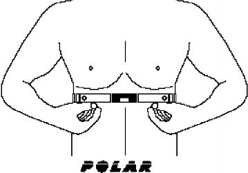
Illustration 14: Correct placement of 789 chest belt
For ca. 85 – 88 % of the subjects the "normal" placement of the transmitter belt is recommended.
In case of transmission problems:
For ca. 10 – 15 % of the subjects the placement "789 LOGO upside down" is recommended.
For ca. 1 – 2 % of the subjects the placement "789 transmitter at the back of the subject" is recommended. However, try the "normal" position always first.
PC-Software H-P-COSMOS ParaGraphics®
The Software H-P-COSMOS ParaGraphics® permits an on-line registration and administration of Heart-Rate-values and endurance-parameters.
The data can be converted by the software and be taken over and evaluated e.g. by EXCEL, 789. Leitner PA 7000 or HRCT software. A take over and processing of the data within a spreadsheet (EXCEL, etc.) or an editor is also possible with the help of the ParaGraphics®.
Further information is available in the separate instruction manual of the software ParaGraphics®.
For the data transmission a connection cable from the Running-Machine to the personal computer is needed. This connection cable is available as optional equipment at H-P-COSMOS (see also optional equipment serial interface).
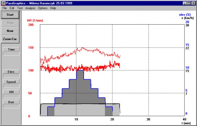
Illustration 15: H-P-COSMOS ParaGraphics® print out Order no. 000 9611 0003 (for all H-P-COSMOS Running-Machines)
Automatic Speed-Control-Function / Position Sensor
(position dependent Speed-Control-Function)
A position sensor (measurement via a thread [yarn] system) is available as an optional equipment. This sensor measures:
the actual position of the subject on the running track
the deviation of the actual position to the target position
According to the deviation of the target position to the actual position the speed of the Running-Machine will be controlled automatically.
11.11.1 Illustration of the running track and the ranges / positions:
Recommended length of the running track: 2000 mm minimum | ||||||||||
C O N T R O L - R A N G E Level 4 | C O N T R O L - R A N G E Level 3 | C O N T R O L - R A N G E Level 2 | C O N T R O L - R A N G E Level 1 | T O L E R A N C E - R A N G E | T A R G E T - P O S I T I O N | T O L E R A N C E - R A N G E | C O N T R O L - R A N G E Level 1 | C O N T R O L - R A N G E Level 2 | C O N T R O L - R A N G E Level 3 | C O N T R O L - R A N G E Level 4 |
Description of Graph:
TARGET-Position: After Start (activation) of the position dependent Speed-Control-Function, the ACTUAL-Position of the subject on the running track will be automatically programmed as the TARGET-Position.
Tolerance-Range: Within the Tolerance-Range the subject is allowed to move freely, without any impact and without any reaction of the automatic Speed-Control-Function. The speed will be maintained constantly.
Control-Range: In the case of the subject moving away from the Tolerance-Range to the Control-Range, the speed of the running belt will be controlled automatically: "faster or slower". The further the subject moves towards the Control-Range (to Level 2, 3 or even to Level 4), the more rapidly the speed will be controlled (accelerated or decelerated/delayed).
The Acceleration-Level and Deceleration-Level can be adjusted via Option 27, (Level 1 ... 6). Pay attention to possible Acceleration-Limitations under Option 10, Option 18 and Option 29!
Control-Characteristic: 3 various settings are adjustable:
Option 50 to 0: If the subject leaves the Tolerance-Range: The speed will be controlled (accelerated or decelerated) until the subject gets back to the TARGET-Position.
Option 50 to 1: If the subject leaves the Tolerance-Range: The speed will be controlled (accelerated or decelerated) until the subject gets back to the Tolerance-Range.
Option 50 to 2: If the subject leaves the Tolerance-Range: The speed will be controlled (accelerated or decelerated) until the ACTUAL-Position of the subject does not move further away from the TARGET-Position.
Commands, Functions, Optional Settings: (and Standard-Recommendation for a running track length of 2500 mm)
Command | Reaction / Description | Recommend. |
Option 26 | adjust Tolerance-Range The value in Option 26 (possible values from 0 20) represents 1/256 x 2 (x 2 is for +/- range) of the total thread length (mainly 3000 mm) of the position sensor. Example: Total Length of the thread: 3000mm divided by 256 = 11.72 mm x 2 = 23.44 Desired Tolerance-Range in this example should be: +/- 200mm (= 400mm) So we need to divide 400mm by 23.44 = 17.06 Enter value "17" in Option 26. Resolution of value is 1.0, so we enter 17 instead of 17.06 | 10 |
Option 27 | adjust Acceleration-Level / Deceleration-Level Program the "sensitivity" of the automatic Speed-Control-Function, how fast/slow the speed should be controlled/changed if the subject is within the CONTROL-Range. Allowed values for this Option: 1 ... 6 ( "smooth" to "aggressive" ) | 3 |
Option 50 | Control-Characteristic for the Control-Range: 1 or 2 or 3 See description above: Control-Range / Control-Characteristic | 1 |
CTRL 4 | START (activation) of the automatic Speed-Control-Function. |
Select and adjust via manual speed control a comfortable speed and a comfortable and safe position (preferably in the centre or within the front 1/3 of the track) for the subject on the running track.
START (activate) the automatic Speed-Control-Function with the command "CTRL 4":
The ACTUAL-Position of the subject will be automatically programmed as the TARGET- Position. | ||
CTRL 5 | TERMINATE (deactivation) of the automatic Speed Control Function. The latest actual speed will be maintained and the Running-Machine can be controlled again manually with the keyboard on the UserTerminal. Reactivation of the automatic Speed Control Function is possible with command "CTRL 4" | |
STOP | STOP running belt and terminate automatic Speed Control Function at the same time. |
Maintenance Regular Inspections / Examinations
Before intervening in the device for safety reasons switch the Running-Machine off and pull the mains plug out!
!
The models H-P-COSMOS MERCURY© LT, STRATOS© LT, MERCURY© LT med and STRATOS© LT med are not equipped with an UserTerminal, so there is no keyboard or display available on these Running-Machines. It is only possible to control these treadmill ergometers via RS 232 interface. With this interface you can use different external equipment, e.g. ECG, Ergospirometry, PC with H-P-COSMOS software ParaGraphics® or H-P-COSMOS Virtual UserTerminal. You can find a complete list of all compatible external equipment in the chapter "List of compatible host equipment.
For maintenance and diagnostics we recommend the PC software H-P-COSMOS Virtual UserTerminal.
As an option an external UserTerminal for remote control over RS 232 is available at H-P-COSMOS.
Preventive Maintenance helps
Our H-P-COSMOS service engineers are happy to help you in the case of occurring problems.
A preventive maintenance can avoid problems in the future and secures the best condition of your device. Therefore ask for an annual preventive maintenance in the shape of a maintenance contract from our service-emergency center at H-P-COSMOS.
Before switching the device on always check the circuit cable, plug, outlet socket and circuit entry of the device.
Immediate maintenance is necessary if
The device has been under high mechanical stress. (push, cable defect through driving over it or pulling it)
Fluid has got into the device.
Cable and / or connector plug have been damaged.
Coverings have fallen off.
Connections made of rubber show cracks.
Only a properly and regularly serviced device is safe.
The maintenance of the devices can also be performed by the H-P-COSMOS-service engineers within the scope of a maintenance contract.
Regular Inspections / examinations
For application in sports and medical areas.
To keep the condition of the Running-Machine in due order examinations have to be performed repeatedly (according to VBG 4. accident prevention directive). An examination interval of one year has been set for Running-Machines.
Those examinations are only to be performed by trained and authorized engineers.
Following examinations are to be performed:
Visual Inspections
Examination of visual damages to the connecting lead and the right position of the tensile relief
Cooling air ducts of the drive motor. the lift motor and of the frequency converter should not be dirty
Coverings for the Running-Machine such as the motor hood and the plastic cover of the installation canal within the motor area should not be damaged
Damaged or illegible warning symbols have to be replaced
All protective-resistance connectors are to be examined for damages and tight fit
Protective-Resistance Measurement
The low resistance pass is to be controlled according to VDE 0701 / 0702 / 0751 by the protective-resistance measurement with a measuring device for the protective-resistance measurement.
The connecting lead is to be moved while measuring for at least 5 sec. If the resistance changes hereby it is highly probable that the cable has been damaged.
Admissible measuring values
Sport Device | Medical Device |
< 0.3 Ohm | < 0.3 Ohm |
Isolation-Resistance Measurement
Make sure that all isolations that are under stress of the mains voltage are being seized. All switches and contactors should be connected.
The measurings are to be performed with measuring devices for the isolation-resistance measurement according to VDE 0701 / 0702 / 0751.
Admissible measuring values
Sport Device | Medical Device |
0.5 mOhm
2 mOhm
Alternative Leakage Current Measurement
The measurement is being performed by a measuring device for leakage current measuring according to VDE 0701 / 0702 / 0751.
Admissible measuring values
Sport Device | Medical Device |
< 7 mA | < 3 mA |
Lubrication of the Running Belt / Running Surface
Take care not to touch the running belt.
This maintenance should be supervised by a second person, who could press the emergency button in the case of danger.
!
Devices without UserTerminal and without automatic Oil-Pump
The devices without UserTerminal are equipped with an automatic oil message via acoustic signal (bleep) indicating the device needs to be lubricated.
On standard setting every 1.000 km after switching on the device (main power switch) the acoustic signal
"5 times LONG (code for "0")" and1 time SHORT + 4 times LONG (code for "1") will be repeated 3 times.
The device has no sensor and the oil message will not terminate automatically after lubrication! The lubrication of the running belt and running surface is done with the enclosed, to the extent of delivery, accessories (bottle of lubricant and 10ml syringe).
After lubrication the oil message has to be terminated with "OPTION 01". An external UserTerminal or a PC-software
"Virtual UserTerminal" is required for this.
Devices with UserTerminal and without automatic Oil-Pump
The devices with UserTerminal are equipped with an automatic oil indication in the UserTerminal display.
On standard setting every 1.000 km the word OIL is flashing in the display. After lubrication the oil message has to be terminated with "OPTION 01". The device has no sensor and the oil message will not terminate automatically after lubrication! The lubrication of the running belt and running surface is done with the enclosed, to the extent of delivery, accessories (bottle of lubricant and 10ml syringe). Use the provided lubricant only! Other available oils and lubricants can damage the running belt and running surface and therefore lead to a breakdown of the Running-Machine.
Lubricant available on request at H-P-COSMOS. The running belt should be lubricated after 1000 km at the latest or after hearing dry grinding noises during operation.
Oiling amount
3 syringes each filled with 10 ml silicone oil
Abbildung 1

1 syringe filled with air
Footboard left | Oil-filling hole | ||
Running belt | Motor- hood | ||
Oil-filling hole | |||
Footboard right | |||
Illustration 16: Oil-filling hole at the left or right hand side
Procedure:
The oil-filling hole is placed between the right (or left) footboard (MERCURY© built 1994 – 1997 at the left hand side of the frame) and the running belt at the front of the Running-Machine.
Start the Running-Machine at a max. speed of 5km/h.
Fill the syringe with 10ml of the lubricant.
Launch the syringe into the oil-filling hole and press the contents slowly in.
Fill the syringe again with the lubricant and slowly press the contents into the oil-filling hole.
Fill the syringe again with the lubricant and slowly press the contents into the oil-filling hole.
Fill the syringe again with air and slowly press the air into the oil-filling hole. This is to empty the small oil-tube of the Running-Machine.
Let the Running-Machine operate for a few minutes at the speed of 5 km/h, so that the oil can spread itself on the inside of the running belt. Walk for 2 minutes at very low speed (ca. 2 km/h) and vary your positions on the running belt, so that the oil under the belt is spread evenly.
Check the position of the running belt after the lubrication. The belt should be in a centre position on the rear roller (tail shaft). In case the belt need to be adjusted please follow the separate instruction.
After lubrication the oil message has to be terminated with "OPTION 01" (see optional functions). The device has no sensor and the oil message will not terminate automatically after lubrication!
The inside of the running belt has a fabric structure and stores the oil till the next interval.
Devices with UserTerminal & automatic Oil-Pump (models "R" for cycle & wheelchair)
Only some of the models H-P-COSMOS VENUS© "R", SATURN® "R" and ORBITER© "R" are equipped with an automatic controlled OIL-Pump and a little tank. The tank is located at the rear position of the machine, close to the drive motor.
The intervals for the automatic OIL-Pump can be programmed (optional functions) via the MCU UserTerminal of the device. Do not change the factory setting of the intervals without prior contact of H-P-COSMOS technical service.
An empty oil tank will be indicated by the code "E55" ("E 01" models with MCU 2) on the UserTerminal as well as a small light indicator at the front of the machine.
Refilling Oil-Tank: VENUS© / SATURN® / ORBITER©
Check if the red oil-level indicator lamp at the front of the machine does light also. If yes:
Remove bellow from upper frame.
Attention! Dangerous voltage and danger of being hurt when the device is open. Do not touch the parts inside the device!
Adjust an elevation of 25 %. Switch off the device on the main switch.
Unplug the mains plug and wait for about 1 minute!
The oil supply vessel (tank) with oil-level indicator can be found next to the drive motor of the device.
Refill original oil available at H-P-COSMOS (about 1 to 1.5 litres, no silicone oil), only.
Plug in the mains plug. Switch on device again.
Adjust an elevation of 0 % and connect bellow again by pressing it against upper frame.
Check if the red oil-level indicator lamp at the front of the machine does not light any more. If it does not light, the refilling was successful.
Erase the message with "OPTION 01".
Set back of oil message MCU 2 / MCU 3
Devices without UserTerminal
An external UserTerminal or a PC-software "Virtual UserTerminal" is required for this. Further instructions see "Devices with UserTerminal.
Devices with UserTerminal
After lubrication the oil message has to be terminated with "OPTION 01"
Control and Tightening of the Running Belt
The belt can loosen after some time of use or when it has been adjusted in a wrong way, so that a backlash occurs with every step between the driving shaft and the belt (slowing down of the belt at weight application through the step).
In this case check the belt tension as follows:
Open the motor hood in the front. Take care that nobody gets their hands into the motor.
Now press the D key to adjust a speed of 1 up to 1.5 km/h.
Stand on the running belt (if necessary with 2 people). Hold on to the side frame with both hands and try to block the running belt by stemming yourself against the running belt rotation with your feet.
Try to block the running belt for max. 10 seconds. The driving shaft and the motor shaft should not be turning during that time. Otherwise the running belt has to be tightened (or the driving belt).
If the running belt is being blocked for too long, then the motor regulation can switch off because of overcurrent, which will be indicated by an error display.
In this case, switch off the device for 5 minutes and then switch it on again.
The belt tension should not have more than 0.5 %, for otherwise it could lead to damages on the belt, on the shafting or the bearings!
Procedure:
The right belt tension is between 0.4 - 0.5 %. That means, that a length mark of 1000mm ( applied on the belt with a pen) on a loose running belt will expand to between 1004 and 1005mm at the right belt tension.
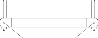
RearRoller (Tail sheave)
Through turning of the left and right adjustment and tightening screws (hex socket 8mm) to the right the correct belt tension will be obtained. The belt can be tightened until the shaft does not turn anymore when running belt is being blocked (see control of running belt tension).
Tension running belt (hex socket 8 mm)
Illustration 17: Tightening of running belt and tightening screw. VENUS© and SATURN® at the front!
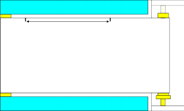
Footboard
Mark of 1000 mm applied when belt absolutly loose.
Tighten belt, until mark expanded up to between 1004 and 1005 mm (= 0.4 to 0.5 %).
Running belt
Footboard
Illustration 18: Mark for running belt tension
Adjustment (centering) of the Running Belt
Attention! Dangerous capture area at the tail shaft at the back of the devices (belt re-entry zone)!
Take care not to be caught with long hair or loose clothes in the capture area of the tail shaft.
For safety reasons the procedure of adjustment has to be supervised by a second person who can press the emergency-stop in an emergency.
Before adjustment of the running belt the belt has to be lubricated, if necessary. Lubrication of the belt may have impact on the centering of the belt. Adjust the running belt while the device is in operation with the help of the left trimming screw at the tail shaft at the back (VENUS© and SATURN® at the front!) of the Running-Machine. Use the enclosed hex socket ( 8 mm ).
Operate Running-Machine at 12 km/h without elevation. Watch the running belt for at least 2 minutes.
The running belt should be in a centre position on the rear roller (tail shaft). If this is not the case please pay attention to the following points.
Move the running belt to the right by turning the trimming screw to the right.
Move the running belt to the left by turning the trimming screw to the left.
If the discrepancy is only minor the screw should only be turned max. ¼, in the case of major discrepancies with max. ½ a turn.
The running belt has to be observed after each alteration for at least 2 minutes. For the purpose of control operate the Running-Machine at 5 km/h and 20 km/h.
The procedure of adjustment is finished if the running belt stays in the centre of the rear roller (tail shaft) after having been operated at a speed of 12 km/h for some time (min. 4 min.).
Uphill run and different other running styles can lead to locomotion of the running belt. +/- 2cm are to be considered as an area of tolerance. As long as the running belt returns to the centre at a speed of 12 km/h it is not necessary to re-adjust. The running belt remains in the adjusted position for a period of months if it has been done correctly.
During "reverse of belt rotation" (downhill run) a readjustment of the belt position (centering) is required.
Through evenly turning the left and the right trimming screw to the right you can tighten the running belt if necessary. See point running belt tension!
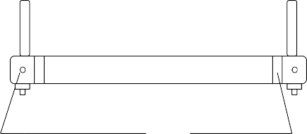
Rear Roller (tail sheave)
Trimming screw (hex socket 8 mm)
Tolerance +/- 2 cm
Illustration 19: Adjusting screws for running belt. VENUS© and SATURN® at the front!
Control and Tightening of the Driving Belt
Driving Belt with Poly-V-Belt system
The poly-v-belt (v-belt) is provided with a belt adjuster and requires tightening usually very seldom. The belt adjuster offers the possibility of re-adjustment.
The driving belt tension can be controlled according to point control of running belt tension.
Block the running belt at speed of 1 to 1.5 km/h.
No backlash must be between the motor shaft and the driving belt.
The noise (at higher speeds) and the straight position of the driving belt needs to be considered.
Driving Belt with Timing-Belt system
Timing belt drives have no automatic belt adjuster. The tension of the timing belt (depending on the model) needs to be adjusted by the manual belt adjuster or by changing the position of the drive motor.
The driving belt tension can be controlled according to point control of running belt tension:
Block the running belt at speed of 1 to 1.5 km/h.
No backlash must be between the motor shaft and the driving belt.
The noise (at higher speeds) and the straight position of the driving belt needs to be considered.
Hygiene, Cleansing, Cleansing of the Interior
For safety reasons switch off the device and pull the plug before cleansing, disinfecting and before opening it!
Pay attention to the instruction manual of the device.
K
Chemicals needed for application or cleansing have to be stored in appropriate reservoirs because of the danger of mixing them up.
Interior Cleansing is recommended in intervals of 6 months.
Unscrew the 5 screws of the front hood in order to lift it. Remove the hood by lifting it up. Remove bellow from upper frame. Models VENUS© and SATURN® do not have a front hood!
Clean the interior of the Running-Machine by removing the dirt with the help of a vacuum cleaner. Pay special attention to the ventilation net of the drive motor.
Cleansing and Adjustment of the Speed-Sensor / Light-Barrier
Depending on the model, the EPROM firmware version and the manufacturing date, the machines are equipped with:
no speed sensor (so no cleansing required)
speed sensor mounted at the back of the drive motor in a separate housing (especially some models VENUS©, SATURN®
and ORBITER©. Since they have a housing there is no cleansing required)
speed sensor (light barrier and slot-disk/incremental glass) mounted at the front of the drive motor. The light barrier of the drive motor is a pulse generator for the control unit.
The light barrier and the incremental glass should be cleansed carefully with a cloth moistened with alcohol in intervals of 6 - 12 months.
In "built in condition" of the glass you can also clean it with the help of a bristle brush which has been soaked in alcohol. Clean the optical elements in between the glass and the light barrier carefully.
Alternatively you can also use a spray (with a thin spraying canal) of fat-dissolving fluid (e.g. braking detergent). The optics of the light barrier will be cleansed by the pressure on the detergent when coming through the spraying canal.
When adjusting the light barrier take care to keep the following guidelines for the spaces between the glass and the casing of the light barrier:
Cleft axial: approx. 1 mm according to illustration
Cleft radial: approx. 1 mm left and right
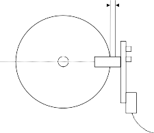
1 mm
Furthermore the imaginary extension of the light barrier has to pass through the center of motor shaft.
Illustration 20: Adjustment of light barrier
Cleansing and Adjustment of the Light-Barrier at Belt-Re-entry-Zones
Especially some models H-P-COSMOS VENUS©, SATURN® and ORBITER© are equipped with light-barriers at the running belt re-entry zone (rear position and front position for the reverse of belt rotation). As a safety measurement the light barriers effect a quick-stop function when the light stream is interrupted by a hand, a falling towel, a coat and of course, also by dust at the glass and/or reflector of the light barrier.
To avoid unwanted switch off (quick stop), the light barrier and the reflector glass should be cleansed carefully with a cloth moistened with alcohol in intervals of 1 week, depending on the air and dust conditions in the room.
Adjustment (direction and focus) of the light barrier can be checked when it is dark in the room.
In case the cleansing of the light barrier does not result in success, you need to check and correct adjustment (direction and focus) of the light barrier. A special small screw driver is required for adjustment of the focus.
Troubles / Malfunctions / Defects
Service Enquiry/Order Form >> Error Message Form >> Brief Check-List
Fax Message to H-P-COSMOS Germany +49-8669-8642-49 Telephone ISDN: +49-8669-8642-0 – eMail: Service@H-P-COSMOS.com – Internet: http:\\H-P-COSMOS.com | |
Company / Clinic / Club | |
Name / Dep. / Function | |
Client No. | |
Street | |
ZIP code / City | |
Telephone / ext. / Telefax | |
eMail / www | |
Business Hours | |
Device Type / Model Name | |
Serial No. | |
Date of delivery/installation | |
Department / Location | |
For safety reasons the Machine should not be operated anymore on suspicion of a technical defect.
Should you eliminate an interference by yourself (pay attention to the legal directions), please inform H-P-COSMOS about it, so that we can register the error in the file of the device and take the appropriate measures.
For safety reasons please switch off the device before taking action and pull the power plug!
Ask the user and a witness and write down the exact description of the malfunction and error codes.


In case you hear noises like knocking or rattling during the training please check if the machine has a firm stand and follow exactly the advises in the chapter "Mechanical Installation" in the manual.
Examine the power supply of the device, try to connect another electric device to the plug of the Machine.
Do not use any distribution boxes or extension cable, but connect the Machine directly with the wall socket.
Has the emergency-stop or rehab-stop been pressed by mistake? Are there safety light-barriers which may lock functions?
Has any key been pressed just before the error occurred?
When and how often has the error occurred up to now?
Which other devices have been in operation at the same time?
Write down the exact indication of all the displays after the error has been detected.
=§!$"%
After the error had been detected, was it possible to immediately start the device again with the „START“ key or did it have to be switched off first?
Immediately inform an authorised dealer and H-P-COSMOS via fax after having answered the above mentioned points.
Actions: | send service engineer send spare parts | Urgent: No Yes by: |
Place, Date |
Signature / Stamp | |
Service Report Form
Fax Message to H-P-COSMOS Germany +49-8669-8642-49 Telephone ISDN: +49-8669-8642-0 – eMail: Service@H-P-COSMOS.com – Internet: http:\\H-P-COSMOS.com | |
Company / Clinic / Club | |
Name / Dep. / Function | |
Client No. | |
Street | |
ZIP code / City | |
Telephone / ext. / Telefax | |
eMail / www | |
Business Hours | |
Device Type / Model Name | |
Serial No. | |
Date of delivery/installation | |
Department / Location | |
Ask the user and a witness and write down the exact description of the malfunction and error codes.


Write down the exact indication of all the displays after the error has been detected.


=§!$"%
Suggestion of measures: | ||
Machine interior room cleansed | Motor / fan grid cleansed | Light barrier cleansed |
Running Belt position adjusted / centered | Driving Belt tension adjusted | Driving belt position adjusted |
Running Belt tension adjusted | Elevation device greased | Elevation device tested |
Platform / running-belt oiled ml | Function test electricity | Function test MCU & UserTerminal |
Function test mechanical system | Test running without subject min | H-P-COSMOS Address sticker fixed |
Calibration of speed | Test running with subject min | Handing over of name card |
Error Messages inverter memory erased | Short operating instruction fixed | asked for Studio / Hospital Brochure |
Performed action: | ||

Spare parts needed
Amount | Description / Serial no. / manufacturing date | H-P-COSMOS Article no. |
Data of machine / MCU UserTerminal
OP 02: km | OP 03: h | OP 04: | h | OP 05: V | |
OP 34: | Max. Speed: km/h | OP 48: | km/h | OP 99 blocked: | |
Comment, notice | |||||
Beginning of work: | Working time: | ||||
Driving distance (one way): | km | Driving time (one way ): | hours | trip Total |
|
place, date | stamp and signature customer | signature service engineer | |||
Mechanical / Noise Problems
In case you hear noises like knocking or rattling during the training please check if the machine has a firm stand and follow exactly the advises in the chapter "Mechanical Installation" in this manual.
Most time a false adjustment of the levelling sockets (adjustable "feet") at the rear of the Running-Machine are responsible for the knocking sound.
Running Belt Adjustment Problems
If the tension of the running belt is not correct it is difficult to keep the position of the belt centered.
In case of reverse direction of the running belt: It is normal that the belts needs to be re-adjusted every time when using this option. Check and follow exactly the advises in the chapter "Control and Tightening of the Running Belt" in this manual.
Fuses
The Running-Machines are equipped with an expulsion fuse at the front of the device / frontal section below the hood. The expulsion fuse for models QUASAR®, PULSAR®, VENUS© and SATURN® is located in the interior section.
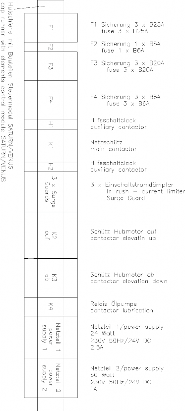
Illustration 21: Fuses model VENUS© / SATURN® / ORBITER©
No Start function / No Elevation function
Check OPTION 22. The Analog interface must be deactivated (OPTION 22 0) if you do not use analog remote devices via analog interface.
Interference Factor
Electrostatic Discharge
If the user moves around the devices they can be electrostatic charged with up to several thousand volts. If then the user touches a metal piece, keys or display, it can lead to an electrostatic discharge between the user and the device.
Electrostatic discharges can in certain cases result in an interference of the device.
Generally those electrostatic discharges are without harm for the user as well as for the device, but can be quite unpleasant. The main causes for electrostatic discharges are the choice of clothes, the sole of a shoe and the movement. Very dry air and many light fittings can also lead to the same results.
Solution: Try different clothes or shoes, humidify the air in the room, switch part of the light fittings off.
Please inform the manufacturer if you detect such an interference.
Source of Interference
The devices should not be installed near to e.g. an x-ray device, motors or transformer with high connection power, as the electric and magnetic interference can falsify measurements.
Very strong sources of interference (e.g. above the limit according to EMT) influence the functions of the device. High tension power lines nearby and electrical devices without c -sign and without a certificate of compliance for electro-magnetic-tolerance should be avoided as well.
Malfunctions of the Heart-Rate-Measurement System 789
Possible sources of interference:
Screens, computer, printer
Electric devices, electric motors, transformer
High-voltage transmission lines, also from trains
Strong fluorescent tubes near by
Central heating radiators
Other electric devices
In order to prevent the Running-Machine being interfered by such factors, place the device at some distance away from such interference sources. Do not rely on the indicated values if you suspect interference!
Please also pay attention to the instruction of the manufacturer 789 concerning interference.
13.8.1 Troubleshooting Heart-Rate-Measurement System 789
Press 7 | Activate: Acoustic Heart- Rate-signal | Press once: ON: Acoustic heart-rate-signal for every beat. This function is normally used to control the regularity of the heart rate or to find reasons for transmitting problems (like mobile phones or computer monitors). For detection do NOT use a POLAR transmitter belt! In this case it can be used to detect foreign interference sources. Press once again: OFF: No acoustic heart-rate-signal |
Malfunctions of the Interface RS 232
The most common causes for problem with the RS 232 – interface are:
Wrong connection cable between the Running-Machine and the periphery
Technical defects of the connection cable or male / female connector
False setting of protocols / driver at Running-Machine or periphery (ECG, PC, Ergospirometry)
False setting of COM port at periphery (ECG, PC, Ergospirometry)
13.9.1 Troubleshooting and testing of the Interface RS 232
Loop-Back Test: For testing the RS 232 of the H-P-COSMOS Running-Machine a special RS 232 test plug including testing instruction is available at H-P-COSMOS. Connect the plug to the RS 232 port and adjust Option 20: 10 A blinking code and the instruction will tell you if input and output of the RS 232 are working well.
PC software H-P-COSMOS ParaGraphics®: If you install the H-P-COSMOS software ParaGraphics® to an external PC you can control the treadmill. If it works you know the Treadmill-Ergometer, the RS 232 interface connection cable and the RS 232 interface card of the PC are working well.
PC software H-P-COSMOS Virtual UserTerminal: If you install the H-P-COSMOS software Virtual UserTerminal to an external PC you can control the treadmill. If it works you know the Treadmill-Ergometer, the RS 232 interface connection cable and the RS 232 interface card of the PC are working well.
Error Messages
Many times malfunctions and error messages are caused by problems with the voltage power supply or lack of service (lubrication).
Check voltage supply. Do not use extension cords or multiway connectors! Connect the machine direct to the socket in the wall. Each machine should have an individual circuit.
Check mechanical parts for any malfunction. Check also for towels or other things which might interfere the drive system.
Check lubrication of the running belt and lubricate if required.
Also contact problems at connectors (loose connections) caused by vibrations can result in malfunctions. So please check cables and connectors for loose connections.
The device has a self-diagnosis which recognises some errors and shows their error messages on the display of the MCU UserTerminal (operating terminal) or the frequency changer / inverter (inside the device).
Error Messages: Devices without UserTerminal
The devices without UserTerminal are equipped with an automatic error message codes via acoustic signal (bleep) indicating the device has a malfunction or needs to be lubricated or regular service.
Example OIL Message:
On standard setting every 1.000 km after switching on the device (main power switch) the acoustic signal
"5 times LONG (code for "0")" and1 time SHORT + 4 times LONG (code for "1") will be repeated 3 times. Error Code list see: Devices with UserTerminal.
The error messages have to be terminated with "OPTION 01". An external UserTerminal or a PC-software "Virtual UserTerminal" is required for this.
Error Messages: Devices with UserTerminal MCU 2 and MCU 3
DISTANCE display | PULSE display | Meaning of message Possible reasons | Possible Solutions / contact H-P-COSMOS to co- ordinate actions. |
E01 | OIL | Machines without OIL-Tank: Lubrication service is due. See chapter "lubrication of the running belt". Machines with OIL-Tank and MCU 2: Oil supply (vessel) almost exhausted (some VENUS© / SATURN®, only) or the KEB frequency inverter is disturbed or switched off due to overload or any other error. Running-Machine is still functioning. | Machines without OIL-Tank: Do the lubrication service (standard every 1000 km ( interval is adjustable) according to instruction and then erase the message with "OPTION 01". Machines with OIL-Tank: Remove bellow from upper frame. Attention! Dangerous voltage and danger of being hurt when the device is open. Do not touch the parts inside the device! Adjust an elevation of 25 %. Unplug the mains plug and wait for about 1 minute! The oil supply vessel (tank) with oil-level indicator can be found next to the drive motor of the device. Refill original oil available at H-P-COSMOS (about 1 to 1.5 litres, no silicone oil), only. Switch on device again, adjust an elevation of 0 % and connect bellow to upper frame again. If the red oil-level indicator lamp does not light, and the oil supply is sufficient, the KEB frequency changer will work incorrectly. In this case contact an authorised service engineer. |
E02 | HELP | Service Interval is due. Running-Machine is still functioning. | Every 5000 km (interval is adjustable) a general service (interior cleansing, checking the driving belt, running belt, etc.) is due. Erase the message with "OPTION 01" and contact authorised service engineer for service. |
E10 | HELP | Stop-Key (Rehab-Stop) was pressed for more than 5 seconds. Or at models VENUS©, SATURN / DISCOVERY: Safety Light Barriers (at belt re-entry zone) have been activated. | Erase the message with "OPTION 01". Check all stop-functions, stop-switches and all safety light barriers at belt-re-entry zones (if incorporated). See separate chapter in this manual. In case the message appears again, contact authorised service engineer. |
E20 | ELE | Elevating element exceeded the max. value (25% or 35%). The combined 0% / 25%or35% contact has been activated. Incorrect measurement of angle of | Contact authorised service engineer. |
elevation. | |||
E21 | HELP | Clean the elevation sensor (light barrier and disk) and check the adjustment of the sensor according to the instruction. Erase the message with "OPTION 01". In case the message appears again, contact authorised service engineer. | |
E30 | HELP | Clean the speed sensor (light barrier and disk) and check the adjustment of the sensor according to the instruction. Erase the message with "OPTION 01". In case the message appears again, contact authorised service engineer. Check also OPTION 48 !! (service engineer only) | |
E40 | EEP | Built-in EEPROM type incorrect. The EEPROM must have the number ....H53..... From version V2.20 (from April 1995) on EEPROMS with the number......H52. will no longer be allowed. | Contact authorised service engineer. Integrate EEPROM with the number.....H53...... (authorised service engineer only) |
E50 | HELP | Error of frequency converter / motor regulation Running-Machine is NOT functioning | |
E55 | OIL | Machines with OIL-Tank and MCU 3: Oil supply (vessel) almost exhausted (some VENUS© / SATURN®, only) Running-Machine is still functioning. | |
E81 | HELP | Emergency-Switch has been activated: Source: Rehab-Stop ("Rehab-Sliding-Hold") at the right. Running-Machine is still functioning. | Check the source for Emergency-Switch-Off. In case of doubts contact authorised service engineer. Erase the message with "OPTION 01". If Running-Machine is not functioning: Contact authorised service engineer |
E82 | HELP | Emergency-Switch has been activated: Source: Rehab-Stop ("Rehab-Sliding-Hold") at the left. Running-Machine is still functioning. | Check the source for Emergency-Switch-Off. In case of doubts contact authorised service engineer. Erase the message with "OPTION 01". If Running-Machine is not functioning: Contact authorised service engineer |
E83 | HELP | Emergency-Switch has been activated: Source: External Emergency Quick-Stop (or Safety Harness with Chest-Belt-System). Running-Machine is still functioning. | Check the source for Emergency-Switch-Off. In case of doubts contact authorised service engineer. Erase the message with "OPTION 01". If Running-Machine is not functioning: Contact authorised service engineer |
E84 | HELP | Emergency-Switch has been activated: Source: Light-Barrier at front belt-re-entry- zone. Running-Machine is still functioning. | Check the source for Emergency-Switch-Off. In case of doubts contact authorised service engineer. Erase the message with "OPTION 01". If Running-Machine is not functioning: |
Elevating element is "blocked" or too slow due to undervoltage, caused by a thin power supply cord (cable).
Elevating element is "blocked" or too slow due to mechanical overload.
Elevation sensor is dirty/dusty or not adjusted properly: Due to lack of signals from the elevation sensor (slot- disk with light barrier) the MCU control board cuts the power supply for the elevation motor.
Check voltage supply. Do not use extension cords! Connect the machine direct to the socket in the wall.
Check mechanical parts for any malfunction. Maybe several persons were standing on the machine for a moment? Check also for towels or other things which might interfere the elevation system.
Remove bellow from upper frame. Attention! Dangerous voltage and danger of being hurt when the device is open. Do not touch the parts inside the device!
Drive motor or running belt system is "blocked" or too slow due to undervoltage, caused by a thin power supply cord (cable).
Drive motor or running belt system is "blocked" or too slow due to mechanical overload.
Speed sensor is dirty/dusty or not adjusted properly: Due to lack of signals from the speed sensor (slot-disk with light barrier) the MCU control board indicates "E30"
Safety delay time (inverter or MCU) is longer than the high acceleration command (SPRINT function or high acceleration level)
Check voltage supply. Do not use extension cords! Connect the machine direct to the socket in the wall.
Check mechanical parts for any malfunction. Maybe several persons were standing on the machine for a moment? Check also for towels or other things which might interfere the drive system.
Remove bellow from upper frame. Attention! Dangerous voltage and danger of being hurt when the device is open. Do not touch the parts inside the device!
Check if the Safety delay time (inverter or MCU) is longer than the high acceleration command (SPRINT function or high acceleration level)
Maybe defective Inverter Drive.
Maybe power supply too weak because of an extension cable, etc.
Check Power Supply and Power Cord.
Order service mechanic
Check if the red oil-level indicator lamp at the front of the machine does light also. If yes:
See chapter in this manual: Maintenance / Refilling Oil-Tank.
Erase the message with "OPTION 01".
Contact authorised service engineer | |||
E85 | HELP | Emergency-Switch has been activated: Source: Light-Barrier at rear belt-re-entry- zone. Running-Machine is still functioning. | Check the source for Emergency-Switch-Off. In case of doubts contact authorised service engineer. Erase the message with "OPTION 01". If Running-Machine is not functioning: Contact authorised service engineer |
E90 | Error Chip-Card-Drive (not all Models) Running-Machine is still functioning (except for the chip-card functions) | ||
E91 | Error Chip-Card-Drive (not all Models) Running-Machine is still functioning (except for the chip-card functions) | ||
E92 | Error Chip-Card-Drive (not all Models) Running-Machine is still functioning (except for the chip-card functions) | ||
E93 | Error Chip-Card-Drive (not all Models) Running-Machine is still functioning (except for the chip-card functions) |
Communication malfunction with Chip-Card
Insert Chip-Card to the Chip-Card-Drive
Replace Chip-Card
Replace Chip-Card-Drive
Order service mechanic
Client number at START and STOP not identical.
Check Chip-Card
Insert the correct Chip-Card
Too many training weeks
Check period of training
Check system date and time settings of the Running- Machine.
Re-programme Chip-Card
Test ident on the Chip-Card not accepted
False Chip-Card in the Chip-Card-Drive
Insert the correct Chip-Card
Set back of error message
Press: "OPTION 01"
For devices without UserTerminal: An external UserTerminal or a PC-software "Virtual UserTerminal" is required for this.
Error Messages on the Inverter Drive ("Frequency Changer")
Many times malfunctions and error messages are caused by problems with the voltage power supply or lack of service (lubrication).
Check voltage supply. Do not use extension cords or multiway connectors! Connect the machine direct to the socket in the wall. Each machine should have an individual circuit.
Check mechanical parts for any malfunction. Check also for towels or other things which might interfere the drive system.
Check lubrication of the running belt and lubricate if required.
Also contact problems at connectors (loose connections) caused by vibrations can result in malfunctions. So please check cables and connectors for loose connections.
Depending on the model and manufacturing date the H-P-COSMOS machines are equipped with different inverter drives.
Error messages generated in response to error conditions are automatically stored in the frequency inverter’s memory. This memory is non-volatile, i.e. the error message information is not lost when the unit is switched off. The system stores several error messages in the order in which they are generated. These messages can be recalled from the error memory and displayed on the parameter unit display.
Error Messages on the Mitsubishi Inverter Drive
For the Mitsubishi Inverter you need a Mitsubishi OPERATOR Terminal incl. Display (available at H-P-COSMOS or at Mitsubishi Electric) or a PC / Notebook connected to the Inverter with a special interface cable and Mitsubishi interface operator. Detailed instructions see also Mitsubishi manual.
The frequency inverters have a large number of protective functions that protect the drive and the inverter itself from damage in the event of malfunctions or other problems.
When one of these protective functions activates in response to an error condition the frequency inverter output is disabled and the motor runs down without external control. The ALARM LED on the frequency inverter lights up, and an error message is displayed on the parameter unit.
You can then select the parameter unit’s MONITOR function to display the error message and the output frequency at the point at which the error condition was registered.
The error message code identifies the condition that triggered the protection function and the corresponding alarm. The Table contains the list of all the possible error codes together with the corresponding protection functions and suggestions for corrective action.
Mitsubishi Operator Display | Meaning of message Possible reasons | Possible Solutions / contact H-P-COSMOS to co-ordinate actions. |
E.UVT | Undervoltage | |
E.OC 1 | Overcurrent 1 (During acceleration) | |
E.OC 2 | Overcurrent 2 (During constant speed) |
Check voltage supply. Do not use extension cords or multiway connectors! Connect the machine direct to the socket in the wall.
Check voltage supply to the inverter.
Check for proper installation of the isolation-transformer.
Check voltage supply. Do not use extension cords or multiway connectors! Connect the machine direct to the socket in the wall.
Check mechanical parts for any malfunction. Check also for towels or other things which might interfere the drive system.
Check mechanism, shaft and belt adjustment.
E.OC 3 | Overcurrent 3 (During deceleration) | |
E.Ou 1 | Overvoltage 1 (During acceleration) | |
E.Ou 2 | Overvoltage 2 (During constant speed) | |
E.Ou 3 | Overvoltage 3 (During deceleration) | |
E.THT | Overload (Inverter) | |
E.THM | Overload (Motor) | |
E.OLT | Overload During fixed speed operation the current limit function was continuously activated and the motor stopped | |
E.BE | Fault of the brake transistor in the inverter was detected | |
E.OHT | An external thermo relay tripped | |
E.PE | Fault of the memory device in the inverter CPU defective | |
E.RET | Restart was not possible within the set number of retries | |
E.CPU | CPU Watch Dog CPU Error | |
E.FAN | Fault of the inverter fan | |
E.PUE | The parameter unit (OPERATOR Terminal) was disconnected from inverter | |
E.GF | A ground fault occurred | |
E.IPF | A short-time power failure occurred | |
E.OPT | Option fault. Stops the inverter output if the dedicated option used in the inverter results in connection (connector) fault. | |
0.00 | Communication error |
Check acceleration/delay ramps: may be too short
Incorporate Brake Resistor
Incorporate Braking Module BU / BU-h
Check for Overvoltage of power supply
Check voltage supply to the inverter.
Check for proper installation of the isolation-transformer.
Check motor capacity: may be too high
Check voltage supply. Do not use extension cords or multiway connectors! Connect the machine direct to the socket in the wall.
Check mechanical parts for any malfunction. Check also for towels or other things which might interfere the drive system.
Check mechanism, shaft and belt adjustment.
Check lubrication of the running belt and lubricate if required.
Compare data and capacity of drive motor and inverter.
Check mechanical parts for any malfunction. Check also for towels or other things which might interfere the drive system.
Check mechanism, shaft and belt adjustment.
Check lubrication of the running belt and lubricate if required.
Compare data and capacity of drive motor and inverter.
Check Brake Time
Incorporate Brake Resistor
Incorporate Braking Module BU / BU-h
Check Air Supply and Fan of the Inverter Drive. If necessary, clean ventilation grid.
Compare data and capacity of drive motor and inverter.
Check mechanical parts for any malfunction. Check also for towels or other things which might interfere the drive system.
Check mechanism, shaft and belt adjustment.
Check lubrication of the running belt and lubricate if required.
Check Motor
Replace motor if defective.
Contact authorised service engineer
Replace inverter
Check Inverter for other error messages or faults
Change Parameter 67: higher
Contact authorised service engineer
Replace inverter
Check Air Supply and Fan of the Inverter Drive. If necessary, clean ventilation grid.
Contact authorised service engineer
Replace inverter
Check connection of parameter unit (OPERATOR Terminal)
Check connectors, wiring and drive motor for short circuit to ground (earth).
Check voltage supply.
Check connectors and wiring.
Contact authorised service engineer
A.) The reset signal of the inverter is on.
B.) Loose connection between PU and inverter.
Remedy:
Switch power off, then on.
Switch reset signal on, then off.
Change inverter.
E & OE. Errors and omissions excepted. Subject to modification.
Error Messages on the KEB Inverter Drive
KEB Inverter F0: has it's own display.
KEB Inverter F4: You need a KEB OPERATOR Terminal incl. Display (available at H-P-COSMOS or at KEB) or a PC / Notebook connected to the Inverter with a special interface cable and KEB interface operator. Detailed instructions see also KEB manual.
KEB | Meaning of message | Possible Solutions / contact H-P-COSMOS to co-ordinate actions. |
Display | Possible reasons | |
E.UP E.U.P. | Undervoltage | |
E.OP | OVERVOLTAGE | |
E.OH | OVERHEAT Temperature on the circuit board > 70°C. | |
E.OC | OVERCURRENT Output current > 200% of nominal current | |
E.OL | OVERLOAD | |
E.bu | "WATCHDOG ERROR" Inverter can not receive commands via BUS/Interface | |
_ | "DISPLAY DARK" | |
E.5X | "ERROR AT SET SELECTION" |
Check voltage supply. Do not use extension cords or multiway connectors! Connect the machine direct to the socket in the wall.
Check voltage supply from the mains.
Check voltage supply to the inverter.
Check for proper installation of the isolation-transformer.
Check Air Supply and Fan of the Inverter Drive. If necessary, clean ventilation grid.
Contact authorised service engineer
Replace inverter
Check mechanical parts for any malfunction. Check also for towels or other things which might interfere the drive system.
Check mechanism, shaft and belt adjustment.
Check lubrication of the running belt and lubricate if required.
Compare data and capacity of drive motor and inverter.
Check connectors, wiring and drive motor for short circuit.
Wait (ca. 2min), until inverter display indicates "nOL".
Reset the inverter and check actual load with Parameter r.//r.8
Check mechanism, shaft and belt adjustment.
Check lubrication of the running belt and lubricate if required.
Check connectors and wiring.
Check Interface and cables.
Replace Inverter if defective
Check FUSE F2 of control board. Replace Fuse if defective.
Disconnect cable of connector 14. If Display glows, check external cables.
Check program and parameters of inverter.
Reload parameters with the correct H-P-COSMOS parameter setup.
E & OE. Errors and omissions excepted. Subject to modification.
Error Messages on the LENZE Inverter Drive
Up to 8 error messages can indefinitely be saved in the storage and can be called up by an engineer.
"LENZE" display | Meaning of message, possible reason | Possible Solutions / contact H-P-COSMOS to co-ordinate actions. |
LU | "UNDERVOLTAGE" The supply voltage of the frequency changer is too weak. | |
OU | "OVERVOLTAGE" | |
OH | "OVERHEAT" The final stages of the frequency changer were overheated. | |
CCr | Frequency changer disturbed | |
Hxx | Error | |
Pr | "Parameter Reset" The parameters were reset to the adjustment made in the factory. Possible reasons: "EMC Smog", electrostatic discharge, spikes in the power supply | |
OC1 | "Short-circuit/Overload" Short-circuit in the system Mechanical overload of the drive, e. g. because of incorrect adjustment of belt and/or the shafts. | |
OC2 | "Short-to-ground" Short-to-ground in the frequency changer, the motor cable or the motor. |
Check power supply.
Do not use multiway connectors or extension leads.
Connect the device directly to the socket.
Each machine should have an individual circuit.
Check voltage supply to the inverter.
Check for proper installation of the isolation-transformer.
Check voltage power supply.
Check voltage supply to the inverter.
Check for proper installation of the isolation-transformer.
Check air supply for the frequency changer and, if necessary, clean ventilation grid or replace ventilator at the frequency changer.
Remove heat accumulation in the motor compartment.
Check voltage increase under "C16" (BOOST) and, if necessary, reduce it a little bit.
Replace frequency changer.
Replace frequency changer.
Check frequency changer and mains voltage.
Delete customer-specific parameters
Reload H-P-COSMOS parameters.
Check frequency changer and electrical system
Check mechanism, shaft and belt adjustment.
Check frequency changer, motor cable and motor.
OC3 | "Overload current during acceleration" Short-circuit or mechanical overstressing of drive, e. g. because of incorrect adjustment of belt and/or the shafts. | |
OC4 | "Overload current during sequence" Overload current during "braking", e. g. during steep uphill or downhill running. |
Check frequency changer and electrical system.
Check mechanism, shaft and belt adjustment.
Check whether the system is mechanically overstressed.
Check whether the system is mechanically overstressed.
Check brake chopper and brake resistor.
E & OE. Errors and omissions excepted. Subject to modification.
Annex
Important Telephone- and Fax Numbers, eMail
H-P-COSMOS Team / Customer Service
Dial the following telephone- and fax numbers for information on date of delivery, service, order of consumption goods etc.
For technical enquiries please have the model type, the serial number and date of installation of your H-P-COSMOS machine
ready.
Technical Hot-Line:
Tel. ISDN Sales: ++49 / 180 / 5167667
Tel. ISDN Service: ++49 / 180 / 5167668
Fax ISDN: ++49 / 180 / 5167669
SERVICE-emergency centre
Tel. ISDN Sales: ++49 / 180 / 5167667
Tel. ISDN Service: ++49 / 180 / 5167668
Fax ISDN: ++49 / 180 / 5167669
Reception of orders for consumptional goods: Tel. ISDN Sales: ++49 / 180 / 5167667
Tel. ISDN Service: ++49 / 180 / 5167668
Fax ISDN: ++49 / 180 / 5167669
Domestic Sales:
Tel. ISDN Sales: 0180 / 5167667
Fax ISDN: 0180 / 5167669
Export Sales:
Tel. ISDN Sales: ++49 / 180 / 5167667
Fax ISDN: ++49 / 180 / 5167669
Address:
H-P-COSMOS® Sports & Medical GmbH Fitness-, Rehab- & Sports-Science-Technology Am Sportplatz 8
D – 83365 Nussdorf-Traunstein / Germany Tel. ISDN Sales: ++49 / 180 / 5167667
Tel. ISDN Service: ++49 / 180 / 5167668
Fax ISDN: ++49 / 180 / 5167669
General Instructions / Safety
This instruction manual is part of the device and should always be accessible.

S
Exact observance of the instruction manual is a requirement for the appropriate operation of an H-P-COSMOS-device.
This sign reminds you of paying attention to the enclosed information and to the manual. It also reminds you of concerns which have to be considered for measurements and connection with other devices.
The safety of your subjects and the compliance to the mentioned accuracy of measurement can only be guaranteed, if the consumption goods, sensors and detectors, described in the instruction manual, are being used.
Absorption-, cleansing- and disinfecting chemicals are only to be kept in the appropriate reservoirs. At the connection of gas pressure container it has to be examined about its MOT-admissibility (TÜV) first.
Pull the plug before cleansing or disinfecting electric devices.
H-P-COSMOS guarantees for the safety. reliability and function of its devices only if:
installation, extension, alteration and repair is performed by people authorised by H-P-COSMOS
the room for installation corresponds to the DIN and VDE installation directives.
the device is plugged in at a socket with a protection system.
the room for installation corresponds to the requirements of the surroundings for the device.
the device after the instruction is being used in accordance with the instruction manual.
The entry of fluid into the device has to be removed immediately by a customer service of H-P-COSMOS and a safety examination has to be performed.
Damaged socket connections, wires and pressure control switches have to be replaced instantly by trained personnel or by persons authorised by H-P-COSMOS.
Instructions for Safety and Operation
The following directives correspond to the in the Federal Republic of Germany acknowledged safety model. Please consider that there may be national discrepancies for other countries.
Electric Safety
Safety Classes
In order to protect the athlete and the training personnel the association of German electro-technicians Inc, (VDE) has published special directives for medical used rooms and electro-medical devices.
Devices with a power supply therefore have to, in order to prevent the passing on of the mains voltage over to touchable metal pieces, be equipped with not only a reliable isolation of the parts being under voltage but also additional safety precautions. The VDE-association divides it into so called safety classes.
Of the, for electro-medical devices, licensed safety classes are mainly used the safety class I (i.e. safety precautions with protective wiring), and the safety class II, (i.e. safety measures without protective wiring but with double isolation):
Devices of the safety class I are devices, where the metallic casing-parts are connected with the protective wire of the line net via the safety contact. In the case of an isolation error the inserted fuse element switches off.
Subject Surroundings
The surroundings of the subject should have a gap of 1.5 m as it has been proofed by experience; this has been laid down here as the surrounding.
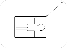
r 1,5 m
Illustration 22: Subjects surroundings
Protection against the Danger of Electrical Shocks
Casing and cover:
Parts of non-medical electric devices within the surrounding of the subject, which, after having taken off the coverings etc. without the use of tools for a routine maintenance etc., are in touchable reach, have to operate with a voltage that does not exceed 25 volt alternate voltage and 60 volt direct voltage, which is produced by a separate source as described in IEC 601-1.
Do not touch such a part and the subject at the same time!
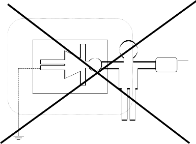
~
electric device
subject
doctor
Illustration 23: Electric devices in rooms
According to this example the leakage current would flow from the electric device to the earthened athlete via the trainer.
Environmental Requirements
H-P-COSMOS devices are not to be used in medically utilised rooms with a danger of explosions or in easily inflammable atmospheres.
The devices should not be installed near to e.g. an x-ray device, motors or transformer with high connection power, as the electric and magnetic interference can falsify measurements or even make them impossible.
High voltage lines should be avoided.
If not stated otherwise in the delivery information H-P-COSMOS-devices are designed for operation in normal climatic surroundings (DIN IEC 601-1):
Temperature: + 10o - + 40o C
Relative humidity: 30 - 75 %
Air pressure: 700 - 1060 mbar
H-P-COSMOS-devices have to be protected from high humidity. Venting slots are not to be covered, otherwise it would hinder the air circulation.
Store the devices at a temperature of - 20o + 50o C.
Symbols used on H-P-COSMOS Devices and may be used on Host Equipment
Symbols used on H-P-COSMOS devices, comply to the according norms IEC 417 and IEC 878.
T Alternating current (AC) M Protection ground N Earth
P Potential compensation
L Devices of the safety class II
S Please pay attention to the accompanying instructions
O Off (supply and connection to the circuit) I ON (supply and connection to the circuit) R Devices of the type B
Q Devices of the type BF
J Dangerous electric voltage






